|
|
|
Close Help | ||||||||||||||
|
|
|
Close Help | ||||||||||||||
|
3a. When things don't work: Making a MPU Test Fixture.
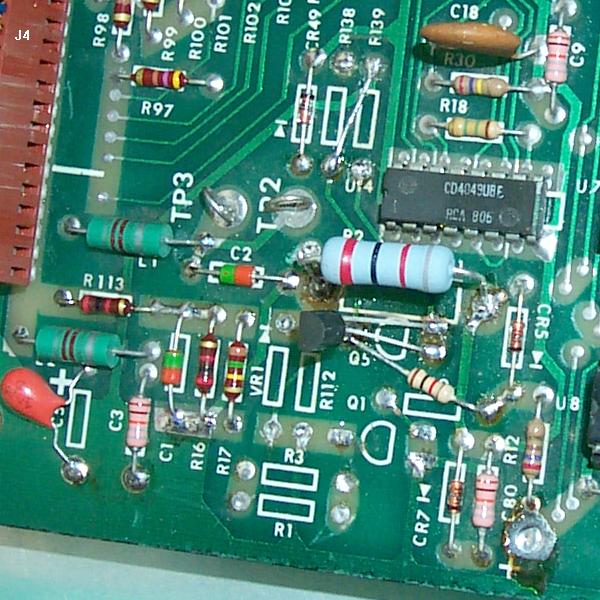
The J4 MPU Board Connector.
Making a Test Fixture.
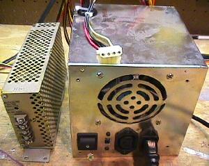
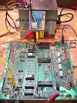
Also remember switching power supplies like the AT and ATX are switch-mode power dependant on load. This means that the power is switched on and off rapidly to meet the load. If there is no load (nothing attached), the output power is switched off. So using a DMM (digital multi-meter) alone to test the power supply output voltages may not be enough draw to make the power supply turn on. In either case, all you need to do is connect the power supply to a wall plug (110 vac), and put aligator clips on the GND, +5 vdc and +12 vdc. That's all you need to power up a Bally MPU board on your workbench! On a computer power supply, the best way to do this is to use one of the plugs that connected to the computer's hard drive, floppy drive, or CD ROM drive. There are usually at least three of these 4 pin plugs on each computer power supply. These plugs have two black wires, and one red and one yellow wire. The two black wires are ground, the red wire is +5 vdc, and the yellow wire is +12 vdc. I used some crimp-on male connector pins and jammed them into the plug. Then I connected these to aligator clips, which ultimately go to your MPU board.
Once you have your test fixture constructed, you can diagnose Bally MPU problems with the flashing LED on the board easily. Instead of putting the board back in the game to test it, just turn your power supply on and count the flashes!
Be careful when you hook up the voltages to your MPU board. If you short +12 volts to +5 volts (for example), you will probably destroy all the chips on the MPU board! Also be careful when you hook up +12 volts to TP2. It is VERY easy to short TP2 to TP3. This may damage the MPU board too! (Unlikely, but let's not risk it). So be careful, and double check your connections before you turn the power supply on.
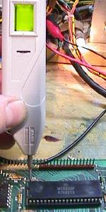
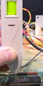
Problems Using the Computer Power Supply. The problem with *some* computer switching power supplies is they take longer than 50 miliseconds to get the 5 volts up and stablized. If you are using one of these slower switchers, a perfectly good MPU board may not boot with that switching powe supply (that is, the MPU LED will be lock on). Until you find a faster computer power supply, you can get the MPU board started by shorting U9 6800 pins 39 and 40 for just a moment (I use a small screwdriver to do this). This simulates the reset section of the MPU board manually, holding pin 40 low for moment. This should start the boot-up process and the MPU LED flashing.
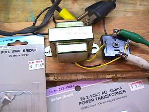
Using the above jig to power a MPU on your workbench will NOT get the last MPU LED "flash" in the power-on sequence. This happens because there is no +43 volts DC present (as used for the solenoids) on the MPU board, which has a circuit to detect this voltage. For most games, this means only getting 6 of the 7 total flashes (for a working MPU). The exception to this is Baby Pacman and Granny and the Gators, which only get 5 of the 6 total flashes. And since the last flash is not achieved, the board won't go into full attract mode. There are *two* ways to solve this problem. The first is to trick the MPU board into thinking the 43 volts is present. To do this, put a temporary jumper wire on the MPU board, connecting chip U12 pin 3 to chip U14 pin 14. This can be done easily with an alligator jumper wire, connecting the top leg of resistor R23 (leg closest to chip U12) to the top leg of resistor R17 (leg closest to TP3). This is certainly the easiest approach. The other solution is more realistic, but involves some parts (a transformer and a bridge rectifier). Radio Shack sells a 120 volt AC to 25 volt AC transformer (#273-1366) for $6 that works well for this. They also sell a 25 amp 50 volt bridge (#276-1185) for about $2.70, which is also needed. To wire this up, connect the two black transformer wires that are together on one side of the transformer to a 120 volt power cord. The remaining three wires (two yellow, one black) on the other side of the transformer are the output. Connect the two yellow wires to the AC terminals of the bridge. The black (center tap) transformer wire you won't use. The bridge should have a label signifying at least one AC lead. The second AC lead is diagonal or across from the labeled lead.
The output from the bridge will be about 25 volts DC. 43 volts DC is not needed because this connects 25 volts to the MPU board's TP3 test point, which is looking for 21.5 volts DC. What happens is the 43 volts DC comes from the rectifier board and goes to MPU connector J4 pin 15. Then the 43 volts goes through resistor R133, which lowers the voltage to 21.5 volts. Then a "zero crossing" voltage detection circuit looks for that 21.5 volts. If present, a working MPU board will flash the last time. If the voltage is missing, there is no last LED flash. So instead of supplying 43 volts to connector J4 pin 15, we just skip resistor R133 and connect our 25 volt DC power supply directly to TP3. It's pretty easy to get a 25 volt transformer, but getting a 43 to 50 volt transformer is more difficult. The zero crossing circuit will work fine if you supply 25 volts DC (instead of 21.5 volts) to test point TP3. The voltage supplied above with the transformer and bridge gives 25 volts DC to test point TP3. This DC voltage is NOT smoothed with a filter capacitor! This is done for a reason. The original Bally power supply doesn't filter this voltage, and for good reason. The zero crossing circuit requires the DC voltage "ripple" to work!
(Re-)Booting a MPU Board with the Test Fixture. 3b. When things don't work: Fixing the MPU (LED flashes and the such).
Skip right to the LED Flash codes by clicking here.
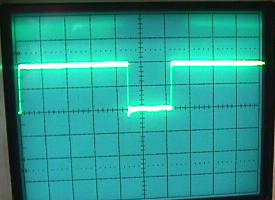
LED Flash Code Introduction and Assumptions. Fixing a Bally MPU board, generally speaking, is one of the easiest game boards you will ever repair. The reason for this, is Bally uses a "LED flash test". The green LED (light emitting diode) lamp is right next to the battery on the MPU board. As the MPU board boots, it does self diagnostics. For each diagnostic test the MPU board runs, it flashes the LED when that diagnostic is complete. If a diagnostic fails, the boot up process stops, and the LED stops flashing. There are a total of 6 or 7 LED flashes during the boot-up process. This makes determining MPU board problems fairly easy.
Preliminary Step: Power. If the LED is lit solid and the MPU is not booting, it can be assumed that the 12 volts is present (because 12 volts is needed to light the LED). So check for 5 volts DC at TP5, it should be in the 4.8 to 5.1 volt DC range. Many times the MPU is locked only because the 12 or the 5 volts are missing or low. If the MPU LED is not lit, check TP2 for 12 volts DC. If 12 volts is there but LED does not (never) lights, cross the two legs (on right side) of Q2 with a small screwdriver. This should turn-on the LED. If it doesn't, assume that the MPU board's LED is bad and replace it. If the 12 volts is missing from MPU TP2, forget about the LED and go to the rectifier board and check for voltage there. The following info applies mostly to games prior to Xenon (where the power supply is in the backbox). But it can be applied to the later games, especially when testing the 12 volt and 5 volt DC circuits of the solenoid driver and MPU boards. Different wire colors may be used in newer games, but the test points (TP) and voltage readings are the same. Check rectifier board TP3 for 12 volts. If missing, check the fuse F3. Remove the 4 amp slo-blow and buzz it out with a DMM. Check the fuse clips for damage or burns, as this is very common. If still no 12 volts DC at TP3, check E11/E12 test points on the rectifier board. These are the two AC inputs and should read about 12 volts AC with your DMM connectors to both E11 and E12. If no voltage check the wiring to the transformer or the transformer itself. If the 12 volts AC is present at E11 and E12, then the bridge rectifier BR2 is open. If fuse F3 blows immediately at power-on, then the bridge rectifier BR2 is shorted. If there is 12 volts DC at TP3 on the rectifier board but no 12 volts on the MPU board, likely it is just one wire causing the problem. Check J3 pin 8 (orange wire) of the rectifier board, as it may be burnt. It is a good idea to replace this connector pin as it handles the 12 volts distribution and is often burnt. Next the orange wire goes to the solenoid driver board connector J3 pin 12. It makes a U-turn and heads back out J3 pin 11 and goes to the MPU board (this is why there is often a jumper between the solenoid driver board TP1 and TP3, to make sure this U-turn does not get cut). At the Solenoid Driver, the 12 volts DC heads also heads to the 5 volt regulator going through the big capacitor C23 (this smooths out the raw 12 volts DC). Often there is a problem with the begative side of cap C23 that causes problems. The negative side of this cap goes back to the Power Supply in a separate wire, independent of other ground circuits. Even though all grounds end up at the same spot, this independent wire helps limit line noise. It also can lead to some weird problems like shutting down the MPU or causing massive resets. This single white/brown return wire goes from the solenoid driver from J3 pin 10 to the rectifier board J3 pin 17. Note that these pin numbers at the rectifier board may not the same the game you are working on. The grouping of the pins at rectifier board connector J3 are often swapped around between pins 1-4 and pins 14-20. These are all ground returns and over the years perhaps the wires were moved. Keep this in mind. The point is if this ground return wire from the solenoid driver board capacitor C23 to the rectifier board gets cut, it will shut down the 5 volt regulator and the MPU. The fastest way to do a check is to jump the left (negative) side of the cap C23 to any ground in the backbox. If the game comes up, you have found a problem with the white/brown wire. You should now have +5 and +12 volts DC at the MPU board, and can start diagnosing the MPU LED board flash codes.
First Step: Count the LED Flashes.
The Last Flash.
No Flashes: the LED is Permanently On. The first and last two points are probably the most common problems.
Go "Bare Bones" (What to Remove for the first "Flicker").
The Reset Circuit. Here's what to try first: If the above happens, the reset circuit is probably working fine. If pin 40 of the CPU is low and never goes high, there is a problem with the reset circuit. Since pin 40 never goes high, the CPU will never start the boot process, and the LED will stay on. Here's some other stuff to try: The above procedure is simulating what the reset circuit is meant to do. If shorting the junction of R1 and R3 does not pull U9 Pin 40 from high to low, then there is a problem with the reset circuit. Most likely there is a problem with Q1 (2N3904), Q2 (2N3904) and/or Q5 (2N4403). Replace them all (they are cheap!) and repeat the above procedure. Also check/replace diode CR5 (1N4148 or 1N914). Finally check/replace diode VR1, which is a 1N959B (1/2 watt) or 1N4738A (1 watt), 8.2 volts (note VR1 is mis-labeled in the manual as "1N9598"). If you still can't get U9 CPU pin 40 to go low, there is some other problem in the reset circuit (corroded traces?). Here are some other points to check. Turn the MPU board on and test: If the above voltages check out, then the reset section is probably working correctly. This means your problem probably lies with chips U6, U9 or U11 (or their sockets), or incorrect MPU board jumpers.
A Reset Trick (LED stuck On) - Adding a Capacitor. It could be the +5 volts is not stablizing within the "window" the CPU expects (about 50ms). To make the reset window longer, try putting a 470 mfd electrolytic capactor in the reset section (on the solder side of the MPU board). Solder the positive leg of this cap to the collector (top leg) of Q1. Then solder the negative leg of the cap to ground (the emitter of Q1). This will increase the reset timing length. Now test the MPU board. If the MPU board works and continues with the flashes, the +5 volts was just not getting "stable" in the 50ms window (there could be a power supply problem, probably with the large 12 volt C23 rectifying capacitor on the driver board). One note about this added reset capacitor. Since the 470 mfd cap increases the reset timing (the time pin 40 of the CPU is held low), the initial "flicker" may not longer be a "flicker". The LED will stay on longer (because the reset is longer), making the "flicker" more of a "flash".
Buy a Bally Reset Section Repair Kit. If for some reason the $4.50/$10 is too much money, here are the typical parts needed for reset section repair:
Using a Dallas/Maxim DS1811 in the Reset Section. Interestingly, the new Alltek Systems replacement MPU board (allteksystems.com) also uses a Dallas-Maxim reset chip. The only difference is their board uses a DS1233 (which is the same as the DS1811, except the reset timing is 250ms, where the DS1811 is 150ms). The Dallas DS1811 comes in three TO-92 flavors of "normal reset threshold": The DS1811 is installed with pin 1 going to /RESET (Q5's leg closest to resistor R11), pin 2 to +5 volts, and pin 3 to ground. If the MPU board boots fine by shorting pins 39 and 40 of the U9 CPU, installing this part may be the "quick fix" to your reset problems. Also the benefit of removing many of the stock reset components on boards with battery corrosion certainly helps. There is a side affect of the changed reset circuit: Since the Dallas DS1811 increases the reset timing (the time pin 40 of the CPU is held low) from about 50ms to 150ms, the initial "flicker" may not longer be a "flicker". The LED will stay on longer (because the reset is longer), making the "flicker" more of a "flash".
Installing the Dallas DS1811.
As Neil explains, replacing resistor R11 is a good idea. These carbon resistors eventually heat up and break down, and once you replace the rectifier circuit with better diodes, the leakage is smaller and that results in around 14 volts on the 11.9 volt line. This is enough to push the stock resistor out of spec. It will heat up and change resistance, and in some cases will go open, which causes a reset. As long as R11 is a 2 watt resistor, it should be fine. If the current resistor is discolored or of a carbon type, it should be replaced.
A "Good" U6: EPROMs, Masked ROMs, and Jumpers. U6 is the program ROM chip which contains the code for the boot-up diagnostics (and on some Stern games, U2 and/or U5/U6 ROMs are also required for the initial "flicker"). If you don't have a good U6, and don't have the MPU jumpered properly for that U6/U2, the diagnostics can't even start to run. If you don't have an EPROM programmer to make your own U6 EPROM, contact Tom Callahan and order the ROMs needed for your particular game. Make sure you plug them into the sockets correctly (notch oriented correctly) when you install them. Also make sure you have the jumpers set correctly for the type of ROMs you are installing.
Don't Change the MPU board's ROM jumpers unless you have to!
Using 2532 EPROMs instead of 9332 Masked ROMs.
A "Good" U9 and U11. If your LED is locked on, and the reset circuit is working (see above), I would next invest in a new 6800 CPU for U9, and a new 6821 PIA for U11. You can buy these for just a few dollars. Get a couple extras of each chip. While you're at it, get a few 5101 RAM chips too (as these go bad a lot on the MPU board).
What Chips are Required to Get the MPU "Unlocked"?
How Can I Ensure I have good U6, U9 and U11 Chips? If you have no spare working MPU, make sure you buy some new U9 (6800 CPU) chips and U11 (6820 PIA) chips. They are inexpensive and worth keeping "in stock". And get a set of known good EPROMS (U6/U2) too. You can buy these from many sources if you don't have an EPROM programmer
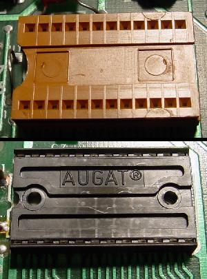
Good Chip Sockets (replace the "closed frame" sockets!)
Sometimes fixing a MPU board can be as easy as taking all the socketed chips out, and re-seating them into their sockets. It's worth a try, as it only take a minute (and costs nothing). Sometimes bad connections can be rectified by doing this. Make sure when you plug the chips back in, that ALL the legs go into the socket and that the chip notch is oriented in the correct direction (a common neophyte error). Plugging a chip in "backwards" usually destroys it. If re-seating the chips does work, this usually means the sockets will need replacing. If re-seating actually fixes something, this mean the socket in question is BAD. No question about it, replace that socket.
As stated above, if the jumpers are set incorrectly for the ROMs installed in the MPU board, the MPU LED will be locked-on. This happens because the ROM code is what turns the LED off - if the MPU can't access and run the ROM code, then the LED will never turn off and start its flash sequence. On the CPU chip U9 pin 5 is the VMA line (valid memory address), and it should never be stuck HI or LOW (it "polls" the U6 ROM). A bad U6 ROM can affect the CPU U9 pin 5's behavior. The CPU's U9 Pin 5 behavior is controlled by U9, but tying it to a bad or mis-jumpered U6 ROM can cause many problems. So if you are confused about the ROM jumpers, try this: Boot the MPU board with only U9 and U11 installed (all other socketed chips removed). The LED will stay on, but using a logic probe check U9 pin 5. It should be pulsing. Power down, add ROM U6 and repeat. If U9 pin 5 is now stuck high or low, U6 is either bad, or you have the wrong jumpers.
The LED is Still Locked On. If the reset section is working, get a head start and put in your own "known good" U9, U6 and U11 (and re-jumper the board if necessary). This will usually get at least a flicker out of the LED. If the LED is still locked on, here's some other things to test: Reset Section Components to Replace: After the Reset Section is Rebuilt, try this:
If you've gotten to this point, and the MPU's LED is still staying lit, you may want to consider sending the board out for repair.
Strengthen the Reset Signal by Replacing Caps C14 and C15.
Was there Work Done on Chips U15 and U16?
More on the RESET Signal and a Locked-on LED.
Q5 gets Cooked by R11, and the Game Re-boots Intermittently.
The Game only Starts up "sometimes".
LED Still Locked On: MPU Board Signals.
All the following signals are with the MPU board in "attract" mode,
and a MPU -35 loaded with Kiss 2732 EPROM's at U2 and U6.
Because these signals are with the game in attract mode, this
chart won't help much if your MPU is in some other state.
This can be caused by a lack of +12 volts getting to the LED, or the LED could be dead. A dead LED happens quite a bit actually. But first trace the +12 volts: If +12 volts is at the above three points (or at least two of them), the LED is probably bad. If you have the above voltages, cross the two adjacent legs of Q2 together with a screw driver. This should light the LED. If it doesn't, and the above voltages exist, replace the LED.
Ok, the MPU's LED "Flickers": What's Next?.
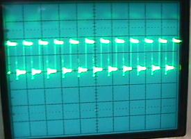
Introduction: The following LED "flash" sequences are indications to the user that the MPU board's components are being tested, and passes these tests. The number of flashes counted can determine very precisely what MPU board component has failed (1977-1984 Williams pinball owners wish they had it this good!) People familiar with repairing Bally MPU boards are indeed very thankful of these tests, as most often they identify the exact problem on the MPU board. Remember, the indication of a particular flash means the part being tested passed. That is, if a MPU board boots with just a flicker and then two LED flashes, this mean the reset section and chips/sockets U6/U9/U11 are good (the flicker indicates they passed), ROM chips/sockets U1 to U6 are good (the first flash indicates they passed), and the U7 RAM 6810 is good (the second flash indicates it passed). Since no third flash was seen, this means the item being tested at the third flash (the 5101 RAM at U8 or its socket) did not pass the test, and therefore no third flash was seen. At this point, the boot-up program locks up, and will not continue testing the MPU board until chip U8 (the third flash test item) is fixed. Of course if the MPU board's LED locks on at boot up with no flashes, this means (as discussed above) that the reset section and/or chips/sockets U6/U9/U11 are bad. At this point, I am assuming the LED is not locked on, and that the reset section and chips/sockets U6/U9/U11 are good (basically that the MPU board at least gives the first LED "flicker").
1st Brief Flicker Completed: Techno Guide: On power-up, the U9 CPU chip requires +5 volts DC be applied before the reset line is allowed to swing from 0 to +4.8 volts. It also requires the presense of a two-phase, non-overlapping clock pulse. If these conditions are met, and if the U9 CPU chip itself is good, the LED on the MPU board briefly flickers. The brief flicker indicates the operation is proper. The MPU has gone out to memory and obtained the starting address of the self-test from memory. The flicker indicates that it then went to that address in the U6 ROM and started to execute the self-test program in the U6 ROM. The Valid Power Detectors circuit on the U9 CPU works with the +5 volts DC regulator Q20 on the solenoid driver board. This prevents the reset line from going high until +5 volts DC is proper at the U9 CPU chip. Q20 is supposed to go into regulation when +7.5 volts DC is applied to its input. This means that when the game is turned on, and a sufficient time (milliseconds) has passed so that C23 on the solenoid driver board has charged, Q20 switches into regulation. This supplies +5 volts DC to the MPU board. Q1 on the MPU board (in the valid power detector circuit) does not allow the CPU chip to turn on immediately. The zener diode VR1, in series with the base of Q1 delays application of the reset voltage until C23 charges. At this point, Q1 and Q5 on the MPU board go into conduction, and the reset line at the MPU is caused to go high. Only then is the U9 CPU chip "on". The importance of the Valid Power Detection circuit can be appreciated when the following fact is known; should the reset line be allowed to go high before the +5 volts is applied and proper, or should the +5 volt supply fail and go out of regulation, the U9 CPU chip can jump out of the program. The reason this happens is that the U9 CPU goes out to the program memory bank U1-U6 for instructions. The logic levels are wrong because the +5 volts is not proper. The MPU misinterprets the data, jumps out of the program, and executes this misinterpreted program! The U9 CPU is now like a train that has left the tracks, and it can end up anywhere. The difference is that a train will eventually stop. But the U9 CPU may continue as long as the clock circuit continues to run. If the U9 CPU jumps out of the program, it is said to be in "run away". While it is mis-interpreting the program, it invariably overwrites the Bookkeeping function in U8 and the scratch pad RAM. An indication of a "run away" would be false data in bookkeeping. Probable cause is a faulty Q20 or C23 (or both) on the solenoid driver boared, or a leaky zener diode VR1 on the MPU board.
First Flash Completed: Techno Guide: the U9 CPU chip next goes out to the program ROM's (read only memory) U1 to U6. It tests each chip in the bank, in accordance to how the MPU board is jumpered. When it finds the bank is correct, it flashes the LED for the first flash. A fault in the U1 to U6 ROM chips is indicated by the absense of the first flash. The U9 CPU tests each ROM chip's function like this: in a game with ROM chips U2 and U6 (typical), the CPU first goes to U2. It fetches the first byte in U2, and adds it to the second byte in U2. It will add to this sum the third byte in U2. This continues until all bytes in the chip have been added up. If the sum of all the bytes is "0000 0000", the U9 CPU proceeds to U6 and repeats this process. If U6 has a sum of "0000 0000", the U9 CPU causes the LED to flash the first time. Fault in either U2 or U6 is indicated by the absence of the first flash. The contents of each ROM chip have byte locations called checksums, reserved for this test routine. There is one checksum byte reserved in each 512 bytes of ROM memory. The game programmer at Bally must insert a btye with the proper value in each checksum byte location to force each 512 byte checksum to equal "0000 0000". During the life of an electronic game, if a ROM chip U1 to U6 fails by so much as a single bit, it will be detected during this CPU test. The CPU will not continue until the defective ROM chip is replaced.
Second Flash Completed: Techno Guide: The U9 CPU chip goes out to the U7 RAM and erases the contents of the first byte (U7 is a 128 byte scratch pad memory). It then tries to read back the word "0000 0000" (indicating erased). If it can read it back, it adds "1" and continues. 256 tries later, it writes the word "1111 1111". If it can read it back, it has determined that the first byte in U7 is good. It repeats this process for each of the 128 bytes of RAM in U7, one at a time. If at the end of this 256 x 128 (=32,768) tests, each time the CPU writes, it can read the same word back, the CPU cause the LED to flash a second time. Note the pause between the first and second flashes. This is the CPU doing 32,768 tests to the RAM at U7 and repeats the process.
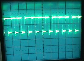
Third Flash Completed: Techno Guide: The U9 CPU goes out to U8 (CMOS 5101 RAM) and makes a copy of the contents of the first half byte. It does this because U8 is battery supplied, non-volatile memory where the bookkeeping functions are stored. It then erases the contents of the first half byte, and tries to read back the word "0000 xxxx". If it can read it back, it adds "1" to the previous word (giving "0001 xxxx"). It continues to write and read until it reaches the word "1111 xxxx". When this is done successfully, the CPU restores the original contents to the first byte located in U8. It then makes a copy of the contents of the second byte, and repeats the process. It does this for the entire 256 bytes, one at a time. If at the end of the 256 x 16 (=4096) test, each time the CPU writes and reads the same word correctly, the CPU caused the LED to flash a third time. Since the 5101 U8 RAM is in the "corrosion zone", here is a quick check of the U8's connection to other components. This will help determine if the U8 socket is bad. (Note the letter/number in parends is the address, or data, or chip enable number.)
If all the U8 RAM lines ring out as described above, and the 5101 U8 RAM is known "good", yet only two LED flashes are received, next replace U19 (4011). This often fixes a stubborn two-LED-flash MPU board. Also be aware of the speed of any replacement 5101 RAM. A too-slow 5101 will may pass the initial boot-up LED code test, but can cause wack score display behavior. Turns out a bad 5101 RAM or one that is too slow will not keep up with the CPU's demand for accessing the display data. Here's a list of 5101 RAM speeds:
The Phillips brand of 5101 is the best, as it's the fastest and will work in all Bally/Stern MPU board applications. Sterns MPU-200 need 450ns or faster RAM, Bally MPU -35/-17 need 650ns or faster. So you can see that some 5101 RAM just won't work properely in Bally or Stern MPU boards.
Fourth Flash Completed: Techno Guide: The U9 CPU chip now tests the first 6821 PIA chip. There are two of these chips on the MPU board, which are identical and interchangable. The test for both is the same. To determine if a PIA chip is good, the U9 CPU does the following: A total of 4 x 256 + 4 (=1028) test steps are required to test the PIA chip. However, there are internal buffer amplifiers used with the PB0 to PB7 output registers and CB2 port register which can not be tested by the CPU. Access is only to the register; if the buffer is open, it does not interfere with the registers ability to be written into and read from by the CPU. It is this uncertainity that reduces the accuracy of these test to 99.5%. Also check and make sure that the MPU connector J1 and the lamp driver connector J1 are not mixed up! These two connectors are about 4 inches apart, and are keyed the same. If only three MPU LED flashes are seen, this problem can also sometimes show the score displays with an '8' or a '9' in the hundreds place. Also I recently fixed a game (Bobby Orr Power Play) where sometimes it would not get the fourth MPU flash, but sometimes it would get all seven. If it did boot, the score displays would flicker and only show some of the six digits. The problem was a trace going to U10 on the component side of the MPU right near the battery that was intermittent from corrosion. After I cleaned up the corrosion (sanded and neutralized) and repaired the broken trace (it was obviously open after sanding), the MPU booted and the game worked correctly.
Fifth Flash Completed: Techno Guide: Same test is performed on U11 as was performed on U10. See above.
Sixth Flash Completed*: Techno Guide: The U9 CPU chip monitors PIA2, port CA1 (U11). If transitions from high to low are detected, the CPU decides the Display Interrupt Generator is working. If U12, a 555 timer, or any associated circuit component fails, the CPU will not flash the LED the sixth time. * Note on Baby Pacman and Granny and the Gators, this flash step is skipped and not tested.
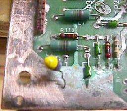
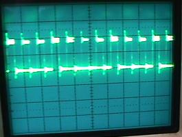
Seventh (Last) Flash Completed**: Remember the 7th flash is looking for 43 volts (or 6 volts AC in the case of Baby Pac's last flash) on the MPU board. Note this test for voltage is performed on Baby Pac too (the prior flash step is skipped, giving Baby Pac a total of 6 LED flashes). This is done thru PIA U10's CB1 port. The PIA is looking for the zero-cross of the 43 volts (or 6 volts for Baby Pac). If 43 volts is not present (rectifier board F4 fuse blown), the last flash will not occur. If the game locks_up after the 7th flash, try unplugging the sound card and reboot. If it then works check the isolation power diode CR3 on the sound card - sometimes this bad diode on the sound board can lower the 43 volts enough to stop the MPU board's 7th flash (Star Trek comes to mind). Also Check the solenoid driver board cap C23 is in good condition. There is also a chance the 555 timer chip and/or C17 could be bad on the MPU board. The 43 (or 6) volts can be "faked" and not supplied (for example if you are booting the MPU board on the work bench), and the last LED flash can happen. Just connect the top leg of resistor R23 (leg closest to chip U12) to the top leg of resistor R17 (leg closest to TP3) using an alligator test lead. Techno Guide: The U9 CPU chip monitors PIA1 port CB1 (U10). If transistion from high to low are detected, the CPU decides that the zero crossing detector is working. If U14 fails and the CB1 line is stuck high or low, the test will also fail. The zero crossing detector circuit input is the +43 volts DC line that is used for the solenoids. If the fuse in that line (F4 on the power transformer module) is blown when the game is turned on, the CPU will not flash the LED the seventh time. ** Note on Baby Pacman and Granny and the Gators there is no 7th LED flash.** These games only had six flashes instead of seven. The easiest way to determine if the MPU board is a -133 designed for Baby Pac/Gators and 6 flashes is to look at the J4 connector (lower left corner) around pin 19. Between L1 and L2 (the very large inductors that look like 2 watt resistors) is either a diode (cr52) or a resistor (r113). If it's a diode, this is a -133 MPU board and there will only be 6 flashes. If it's a resistor, it is a -35 or -17 MPU board and there should be 7 flashes. Converting the -133 MPU to a -35 MPU is very easy do. Just replace the 1N4148 diode at CR52 with a 2k ohm 1/4 watt resistor. New EPROMs will need to be burned too of course For more information on the -133 MPU board see here.
Game Initialization.
Problems/Solutions with the Seventh Flash. If fuse F4 is blown on the solenoid board, the seventh flash will not occur. But what if there is a problem on the playfield which is forcing this fuse to blow (stopping the final LED flash on the MPU board, hence stopping your MPU diagnostics)? The easiest way to deal with this is to remove the solenoid connectors from the solenoid driver board to the playfield. These connectors are on the left side of the solenoid driver board, and the one connector at the bottom right of the board too. This should allow the F4 fuse to be replaced, and the completion of the MPU booting process. To help find the playfield coil that is causing the F4 fuse to blow, replace the connectors one at a time on the solenoid driver board (with the game off), and reboot the game. This will help issolate the bad coil. Another thing to try: remove the under-the-playfield coil fuse, and replace fuse F4. If F4 does not blow, then one of the coils under the playfield is somehow shorted or staying energized (and blowing the solenoid driver F4 fuse). If fuse F4 still blows, there is either a problem with the backbox knocker, or the cabinet coin door lockout coil, the solenoid bridge rectifier (on the rectifier board), or the rectifier board's varister. Also try removing connectors J1 and J3 from the rectifier board (this moves the solenoid power back a step further, not allowing it to get any further than the rectifier board). Replace fuse F4 on the solenoid driver board, and turn the game on. If the fuse still blows, the solenoid bridge rectifier (on the rectifier board) or the rectifier board's varister is probably at fault. If it is a coil under the playfield, check the coils to see which one energizes when the game is powered on. Or disconnect a wire on each solenoid, and re-attach each wire, one at a time, until the fuse blows. At this point it could be the coil, coil diode, or coil driver transistor at fault.
Still No Seventh Flash - Other Things to Check.
Faking the 7th Flash. To fake out the MPU board, use an alligator jumper wire and connect the top of resistor R23 (leg closest to U12) and the top of resistor R17 (leg closest to TP3). This makes the MPU think the 43 volts is present, and will allow the board to fully boot (7 flashes). This happens because the 43 volts is reduced to 5 volts and then converted into an "impulses train". This signal comes from pin U10 pin 18 and then the MPU monitors this impulse train signal. If the signal is present the MPU thinks the 43 volts must be Ok. By making the connection between the tops of R17 and R23 we simulate the presence of the 43 volt impulses train.
Problems After the 7th flash (game sitll doesn't work). Stern MPU-200 boards in particular can have problems where the seventh flash is seen, but the game does not work. Of course the first thing to check (especially on multiball games) is if all the pinballs are installed and the ball trough switches are working. If there is a single dip switch on anywhere, the MPU boots (seven flashes), then some score digits on all displays come on for about five seconds, then all displays go out (display blanking). Slam switch (and its capacitor) are not the problem! So what could be the problem? The answer is usually a bad 5101 RAM chip. Especially on Stern MPU boards, the 5101 RAM chip(s) need to be the proper speed (100ns, unlike Bally which can use a 300ns 5101 RAM chip), or the game will not work (even though it passed the 5101 self-test at power-on).
MPU Boots Fine, but after Turning Off and Immediately back On, The MPU board
is Locked. The first thing to suspect is MPU battery corrosion in the reset circuit. Inspect the board for any damage due to corrosion. The problem may be the reset line stays high from the battery power. When the battery is discharged enough, the game will restart. This can happen from the two 8.2k resistors (R1, R3) at the bottom of the MPU board. Other resistors in the reset section should be checked too (R2, R112, R120, R140, R139, R138, R140, R12, R11).
Seven Flashes Constantly Repeats. But besides that, if all -32 MPU board DIP switch are off, the game goes in self-test mode (toggling alternatively every solenoid, flashing controlled lamps and testing single digit at a time on every display) after the seventh flash. 3c. When things don't work: Test EPROM & Fixing a Dead MPU board.
That's about all that is needed (all other socketed chips can be removed to minimize problems, and can be added one at a time after the board is running the Test EPROM to confirm their validity, or all the chips can be left installed if desired). The reset section of the board doesn't even need to work - instead we can do a "manual reset" by jumping TP5 (+5 volts) to CPU U9 pin 40 to get a the processor running. The Test EPROM only needs the 6800 CPU at U9 and the reset/clock circuits. It is not dependent on memory chips U7 (6810) and U8 (5101), and the game-specific EPROMs (U1, U2, U5, U6). And the PIA chips at U10 and U11 don't need to be installed (even though the Test EPROM will try and test these two PIAs). The Test EPROM has a short program which runs from EPROM U6 and controls the two PIA chips at U10 and U11. Basically it sets the U10/U11 PIA chip outputs PA0-PA7 and PB0-PB7 and CA2/CB2 high and low, over and over at one second intervals. While it does this it flashes the built-in MPU LED at one second intervals and a Test LED which we will connected to CPU U9 pin 15. This gives us the opportunity to test the PIA outputs using a Test LED or logic probe or even a DMM. The Test EPROM does not care if the chips are working or not, and it does not care about the other memory chips on the board either. It will try and run this test over and over regardless, unlike the built-in Bally/Stern test which will stops as soon as it finds a problem. This allows us to get the MPU board working with a mimimum of chips (and a minimum of problems). Remember it is always easier to tackle a small set of problems, instead of trying to find all problems at once. If a MPU board can run Leon's Test EPROM, you are well on your way to fixing the MPU board. It is always the initial step of making a MPU board boot on its own that is most difficult. Problems past this tend to be easier to tackle.
Download the Test EPROM files here and burn them into a 2716 EPROM:
Using the Test EPROM. With the power off, remove MPU board chips U1, U2, U5, and U6 (the game ROMs), also U7 (6810) and U8 (5101). Note all these chips do not have to be removed, but it's a good idea to minimum potential problems by removing them. Also remove the two 6821 PIA chips at U10 and U11 (again not necessary, but a good idea). Because the Test EPROM is a 2716 EPROM, the MPU board need to be jumpered for 2716 or 2732 EPROMs. Or if you have a MPU board with its original black 9316 ROM chips, the easiest thing to do is to make an adapter as shown in the 9316/2716 Adaptor section of this document (note only one of the two sockets is needed, and the test clip does *not* need to be connected - see the description below). Instead of making MPU board jumper changes (which could be mistakenly done wrong, making the MPU board more difficult to fix), using a 9316/2716 adaptor socket is a much better idea. If the MPU board is jumpered for 2732 EPROMs that is fine - this 2716 Test EPROM will plug right in without any jumper changes and work. The 9316/2716 adaptor for this application takes two good quality (machine pin) 24 pin sockets, and sandwiches them together. There are a couple pins that need to be cut and jumper wires added:
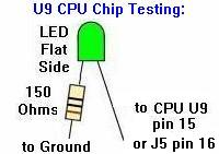
The Test LED. The Test LED will be connected to address line 6 of the 6800 CPU chip (U9 pin 15 or MPU connector J5 pin 16). Take a LED and a 150 ohm resistor connected to the "flat side" of the LED leg. The resistor side of the LED is connected to ground (TP4), and the non-resistor side of the LED is connected to U9 pin 15 or J5 pin 16. Use micro-clips to attach the Test LED.
Using the Test EPROM. Power up the MPU board (ideally on the work bench using a computer power supply for +5 volts to TP5, +12 volts to TP2, and ground to TP4. The Test LED will immediately start flashing about once a second. If the Test LED flashes in rhythm then the reset section of the MPU board and the Clock circuit are working (a very good sign). Note the on-board MPU mounted LED will be locked on if PIA U11 is missing or bad. If the Test LED is not flashing: Probably the reset section of the MPU board is dead or the MPU board is not jumpered correctly for the U6 EPROM installed. To check the U9 reset, with the board power on, use a DMM and check for +5 volts at U9 pin 40 (this is the reset pin of the 6800 CPU chip). If less than 2 volts, the reset is being held low, and the reset circuit of the MPU board is not working (the reset circuit should hold U9 pin 40 low for about 50 miliseconds, and then bring U9 pin 40 high to 5 volts and keep it high - this will start the CPU chip). If U9 pin 40 shows 5 volts, then the reset section is working. If U9 pin 40 is low and you want to simulate the reset circuit with a "manual reset", power the board on. Then use a jumper wire and jump TP5 (+5 volts) to CPU U9 pin 40. This will make the CPU chip's reset line "high", and it should start the CPU running (assuming the CPU chip itself is good, as are all the address and data lines to the U6 ROM). If a "manual reset" does not wake up the CPU, try another 6800 chip at U9. Still no LED flashing? Checking the signals of the U9 CPU chip:
If any of these signals are bad (and the U9 6800 was replaced with a known good one), trace the bad signal to its source and repair it using the schematics. A last possibility is that the ROM selection of U6 doesn't work. Check the following pins of U6:
If all these signals are good, there should be a flashing Test LED (again, with PIA chip U11 removed, the on-board MPU LED will be locked on). Once the LED is flashing, replace the PIA chips U10 and U11. With U11 installed, the on-board MPU board mounted LED should flash in rhythm (but opposite) with the Test LED.
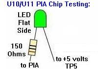
Testing the PIAs Using the Test LED.
If one PIA output does not flash, temporarily connect it (short it) with the output pin next to it. This will cause one of two things - Both outputs "dance": this means the first output is dead and the 6821 must be replaced. If both outputs do not "dance": there is an short somewhere on the suspect output line. If this is the case, disconnect the output line by bending the PIA pin up and out of the socket, and connect the Tester LED to the extracted pin. If the LED dances, the 6821 PIA is OK and the short is somewhere on the MPU board. If the extracted PIA pin does not "dance", then the 6821 is dead and must be replaced.
Finishing Up.
Memory Test using the Test EPROM. Note there are some restrictions to the Memory test. Although Bally and Stern cpu boards can be interchanged, there is a major difference between the -17/-35 Bally MPU board and the Stern M-200 MPU board. The Stern M-200 has an extra 5101 memory chip extra at U13. To make both types of boards use the same memory test, Leon used some tricks in programming the test EPROM. If this wasn't done, and you're testing a Stern board without U13 (or with a bad U13 chip), it would be reported as OK, because a regular Bally board doesn't contain a U13 chip. When the Test EPROM is started, the Test LED will start to light in rhythm, and this is the regular PIA test. Now push the MPU board mounted red button. The Test LED will turn off and after one second it should flash a first time. This means the test of U7 6810 has succeeded. Again a second later the Test LED should start flashing continually (indicating a good "second flash"). The test has run on U8 (5101) and U13 (5101) and has succeeded. But if the LED flashes this second time 5 seconds after the first flash, this means the test has succeeded but *only* for U8. So on a Bally board both flashes have to be about 5 seconds apart, meaning both U7 (6810) and U8 (5101) are good. On a Stern M200 board the second flash (continual flashing) has to be just one second after the first flash, meaning U7 (6810) and U8 (5101) and U13 (5101) are all good. But if the second flash comes 5 seconds later, then the M200's U8 is fine but U13 is bad (you can test this by removing U13, or swapping U8 and U13). So when testing, if U7 or U8 is defective there'll be no flash, or only one flash. If you have a Stern M200 board and two flashes (continual flashes) are seen with 5 seconds between them, then U13 is not installed or U13 is bad. This way one test EPROM can be used for either a Stern M-200 or a Bally -17/-35 MPU board. Another restriction of this memory test (not the PIA test) is that it cannot use a 9316/2716 adaptor socket. When using the adaptor socket it's not possible to use U7 6810 (check the repair manual for Bally Stern MPU boards). Because if only two flashes are seen with the game ROMs installed, there's is a problem with memory chips. But unfortunately the Bally test does not say which memory chip (U7 or U8). So if you don't want to adapt your MPU board to use EPROMs, you cannot use the Leon Test EPROM for the memory test (but the PIA test works fine).
All Done. 3d. When things don't work: Game ROMs, EPROMs, and Jumpers - the Basics
Bally has provided us with about 35 different "jumper" locations on the -35 (and -133) MPU board, and about ten on the -17 MPU. This was done to handle all the different game ROM (read only memory) chip configuations, for all the different games. Depending on supply and demand for certain ROM chips, Bally pretty much had all the bases covered. They could use any combination of ROM types and sizes to fit their needs.
Important: Before you Change any Jumpers!!
Which MPU board Is It: -17 or -35 or -133? (How to Tell!) Basically there are two flavors of MPU board: the -17 or -35 (the -133 is really a -35 board with R113 changed to a diode CR52). The easiest way to tell which board is to examine connector J5. On a -17 MPU board, this connector will have 32 pins (including the removed "key" pin). On a -35/-133 MPU board, J5 will have 33 pins (including the removed "key" pin).
Bally/Williams' Jumper Information.
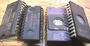
Masked ROMs versus EPROMs. EPROMs are basically the same as masked ROMs, but have a small cyrstal window on top of the chip. If UV (ultra-violet) light is shined through this window, the chip can be erased and re-programmed. An EPROM programmer is necessary to re-program an EPROM. These attach to your computer (though there are some stand alone ones too), and can "burn" a blank EPROM with a game's program code. After the EPROMs are burned, a sticker is placed over their window to prevent light from erasing them. EPROMs are the best replacement for your old and tired black masked ROMs. Chances are if you are doing any repairs to a Bally MPU board, and you need new game ROMs, you will be installing EPROMs. EPROMs are available blank from many sources. But you need to have them "burned" first before you can use them.
The memory inside each ROM or EPROM is the heart of your game. It contains the power-on diagnostics, the switch matrix, the game rules, and the coil assignments, among other things. Each model of pinball game has different program code that must be installed only in the game it is designed for. The program code is stored (burned) in your game's ROMs or EPROMs.
The Jumpers. The wide array of jumpers Bally provides is very confusing. Some games use just one ROM at U6. Others use three ROMs at U6, U2, and U1. The size and type of these individual chips can change too.
What Type and Size are My ROM chips?
Texas Instruments TMS2716 Warning.
What if I don't have an EPROM Programmer?
Using 2532 EPROMs instead of 9332 Masked ROMs.
What Do the Masked ROMs Chip Numbers Mean? Note the higher -xx number means a later revision. In the case of the U6 chips, that revision is important, as generally a game can not be run with the "wrong" U6 part. But for the U1/U2 chips, it usually means a later version of the same game (and all the chips must be of the "correct" revision to match the others, though there's not always a good way to know what that is). As an example, Lost World uses "720-28" for U6. But then the other chips should all be "729-xx", with the latest revision being "729-33" at U1, and "729-48" at U2. If the game has an earlier version, they would have some other numbers after "729-". But note there can be no mixing of old and new versions!
Do I have the Right Jumpers/ROMs Installed? On the CPU chip U9 pin 5 is the VMA line (valid memory address), and it should never be stuck HI or LOW (it "polls" the U6 ROM). A bad U6 ROM can affect the CPU U9 pin 5's behavior. The CPU's U9 Pin 5 behavior is controlled by U9, but tying it to a bad or mis-jumpered U6 ROM can cause many problems. So if you are confused about the ROM jumpers, try this: Boot the MPU board with only U9 and U11 installed (all other socketed chips removed). The LED will stay on, but using a logic probe check U9 pin 5. It should be pulsing. Power down, add ROM U6 and repeat. If U9 pin 5 is now stuck high or low, U6 is either bad, or you have the wrong jumpers.
Game ROM Software.
* Go to the Bally Repair Guide Part 1 * Go to the Bally Repair Guide Part 3 * Go to the Pin Fix-It Index * Go to Marvin's Marvelous Mechanical Museum at http://marvin3m.com |
|||||||||||||||||||||||||||||||||||||||||||||||||||||||||||||||||||||||||||||||||||||||||||||||||||||||||||||||||||||||||||||||||||||||||||||||||||||||||||||||||||||||||||||||||||||||||||||||||||||||||||||||||||||||||||||||||||||||||||||||||||||||||||||||||||||||||||||||||||||||||||||||||||||||||||||||||||||||||||||||||||||||||||||||||||||||||||||||||||||||||||||||||||||||||||||||||||||||||||||||||||||||||||||||||||||||||||||||||||||||||||||||||||||||||||||||||||||||||||||||||||||||||||||||||||||||||||||||||||||||||||||||||||||||||||||||||||||||||||||||||||||||||||||||||||||||||||||||||||||||||||||||||||||||||||||||||||||||||||||||||||||||||||||||||||||||||||||||||||||||||||||||||||||||||||||||||||||||||||||||||||||||||||||||||||||||||||||||||||||||||||||||||||||||||||||||||||||||||||||||||||||||||||||||||||||||||||