|
|
|
Close Help | ||||||||||||||
|
|
|
Close Help | ||||||||||||||

Repair from 1977 to 1980 by cfh@provide.net, 03/02/09. Copyright 2006-2009, all rights reserved. Scope: Includes Gottlieb first generation of solidstate System 1 pinball games from Cleopatra (11/77) to Torch (2/80).
Internet Availability of this Document.
IMPORTANT: Before Starting! Table of Contents
2. Before Powering On:
Bibliography and Thanks.
|
|
1a. Getting Started: Tools and Schematics
Tools and Experience Needed.
Schematics. Ni-Wumpf sells a replace System1 CPU board available at www.pbresource.com/ads/adsys1cpu.jpg. Pascal Janin also sells some new system1 boards. A list of his boards can be seen at www.geocities.com/system80pins/pascal.html
1b. Getting Started: System1 Games List, Numbers
1c. Getting Started: System 1 Parts to have on-hand Here a list of system1 parts I like to have on hand for repairs.
See the Parts Suppliers section of this web page for places to buy these parts. 1d. Getting Started: Gottlieb System1 Introduciton
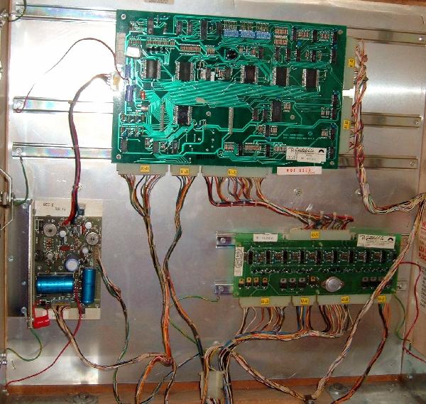
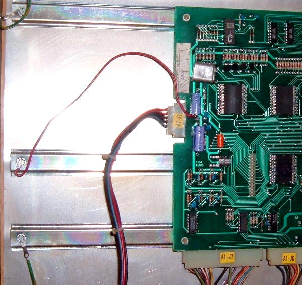
Introduction. The System 1 technology is simple, as Gottlieb did not use solidstate parts for anything that could be done with EM technology. This was unlike Bally and Williams who couldn't abandone EM hardware fast enough. In a System1 game, there are three circuit boards in backbox: a power supply, a CPU, and a driver board. Additionally there is a sound board in the lower cabinet of games Close Encounters and later. Score and credits were displayed using big blue Futaba fluorescent low-voltage displays. This was unlike Bally and Williams gas discharge which used 190 volt displays. This Gottlieb decision was perhaps the best one they made in regards to their solidstate pinball system, as the low-voltage score displays lasted much longer and didn't require a robust power supply.
System1 was Gottlieb's first series of solid state pinballs introducted in late 1977. Gottlieb was the manufacturer leader in EM (Electro Mechanical) pinball. But they had a hard time making the transition to solidstate pinball. They were also the last manufacturer of the big four (Bally, Williams, Stern, Gottlieb) to switch to solidstate technology, and even made some games in both solidstate and EM formats until 1979 (where the other manufacturers had abandoned the EM pinball format since 1977). Bally and Williams had been working on solidstate architecture for since about 1975, and fully adopted the technology by early 1977. Gottlieb on the other hand hired Rockwell to design their solidstate pinball boardsets, and were the last to enter the solidstate market. This was a mistake that Gottlieb endured for over 10 years, as Rockwell did not serve Gottlieb well.
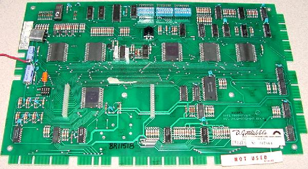
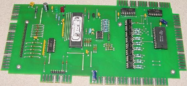
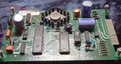
The Rockwell PPS-4/1 and PSS-4/2 system was a 4-bit parallel processing system with two CPU "spider" chips that communicate with each other (U1 11660-CF was the main processor, and U2 10696-EE was the second processor). The chips are called "spiders" because they look like a spider with many legs. The spider chips were a wider chip package, almost a square chip. System 1 used six of these custom spider chips labeled U1 to U6: two for the CPU (U1/U2) and one each for the switch matrix (U5 A1752-CF), solenoid control (U4 A1753-CE), and score displays (U6 10788-PA). The last spider chip (U3, also a 10696-EE chip, same as the second CPU processor at U2) was used for lamps and a few switches and left over duties. Both the switch matrix (U5, A1752-CF) and solenoid control (U4, A1753-CE) spider chips have built-in ROM software. Display output was controlled by the U6 spider chip (10788-PA). The switch matrix has eight rows (R0-R7) and five columns (S0-S4), for a total of 40 switches. These are all driver by chips Z8 (strobes/columns, 7404) and Z9/Z28 (rows, 7405).
Here's a summary of the spider chips: * Note that spider chips U4 or U5 contain the game operating system ROM, and must be of the same revision. These are the two spiders that fail the most. The revision levels that work together are:
Here's a summary of the CPU board connectors: The CPU board keeps high scores and audits in a 5101 RAM (at Z22), which maintained power using a NiCad "Data Sentry" battery (though some System1 CPU boards used a Bally-style AA sized NiCad). These batteries die and leak their corrosive liquids easily, causing much CPU board and connector damage. The game PROMs (where the game specific rulesets are stored) are masked ROMs and the blanks and the equipment to program them is generally not available. PROMs were identified by letters from "A" to "R", including a "T" test PROM. There are EPROM replacement boards that plugs into this PROM's socket to solve this problem. On the CPU board, always check TC3 (test connector three) jumper plug, as it carries the -12 volts to the CPU board which is required by the CPU spider chips and the coil drive circuit. Also the 5101 RAM easily fails. Any weird problems with high score and the 5101 RAM is probably bad. The self test circuit for the RAM is highly suspect and often passes a bad RAM. TC1 and TC2 can be ignored as they are used for internal factory testing. If these fail they do not affect anything. Switch 25 (red button switch at top of board) is the high score reset only.
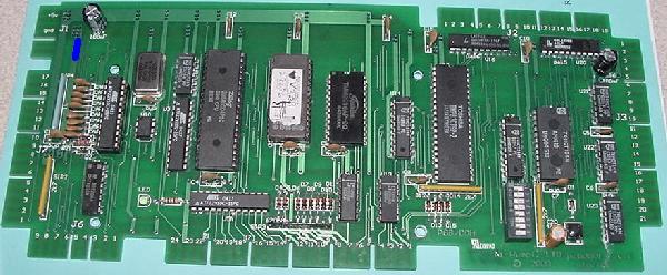
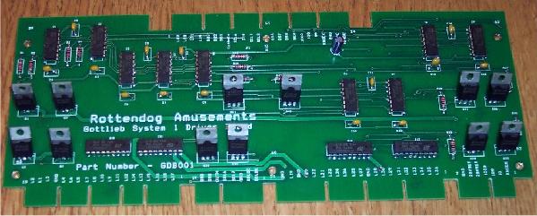
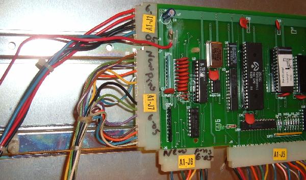
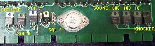
The System 1 driver board could control only eight devices, which included three sound controls (three chimes or three inputs for a sound board), a knocker, and an outhole solenoid. That left only three CPU controlled solenoids for the rest of the game (again, perhaps a drop target reset coil and an eject hole coil)!
Here's a summary of the driver board connectors:
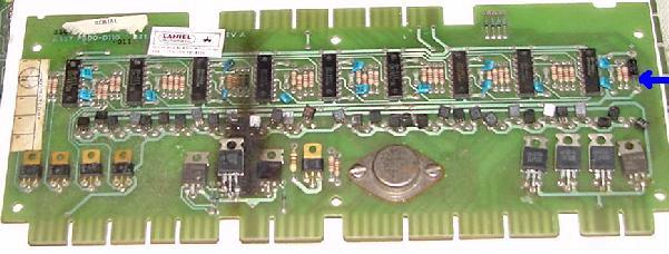
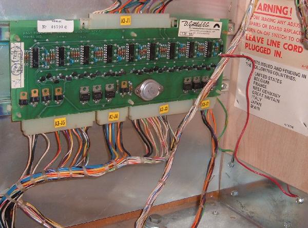
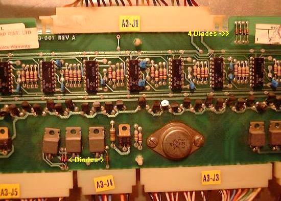
Under Playfield Mounted Transistors (Extension of the Driver board).
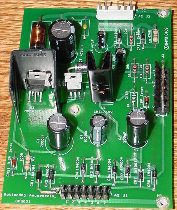
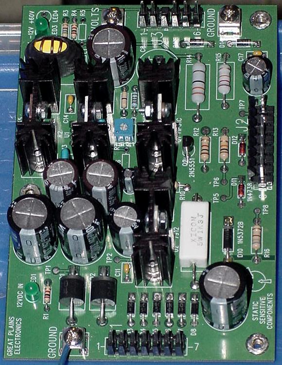
System 1 power supply gets power directly from the transformer at the bottom of cabinet. It consists of rectifiers and regulators to create the various output voltages of +5V, -12V, +8V, +4V, +60V and +42V. Rottendog Amusements makes an excellent replacement System1 power supply for about $65. An excellent value, the Rottendog P.S. works great and is plug & play. Also Great Plains Electronics (GPE) has a really nice replacment System1 power supply.
The bottom panel in the lower cabinet of a System1 pinball houses the two main power transformers, the main fuse bank, the copper ground bank (where all ground wires originate), the RF filter and auxiliary 120 volt service jack, a bank of four diodes (for the coin door switches), and two bridge rectifiers (one for the 24 volt solenoids and the other for the 6 volt CPU controlled lamps).
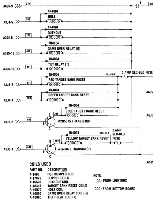
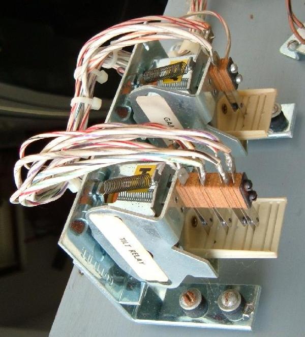
Every System1 pinball has two relays mounted under the playfield. These are the Game Over Relay (Q), and the Tilt Relay (T). The Game Over relay activates and stays energized all during a game. This turns the 24 volt power on for the flippers, pop bumpers and slingshot coils. It also turns off the Game-Over light in the backglass. On Bally and Williams games this relay is on the solenoid driver board, and has a plastic cover to protect it. But Gottlieb felt it should be more accessible, and mounted their Game-Over relay (or flipper relay as Bally/Williams call it) under the playfield. The advantage to this is the relay is more accessible, but it's also more easily damaged or knocked out of alignment or the switches mis-handled. The T-relay is the tilt relay. This comes on when the game is tilted, and stays energzied until the current ball is drained into the outhole. This relay disables the power to the coils and flippers, and turns off the computer controlled lighting power to the game. It also turns on the Tilt light in the backglass.
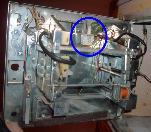
In the three first System1 games there was a three tone chime unit, as used in Gottlieb's EM games. With Close Encounters this changed to a simple tone generator sound board, which still used the same three driver board transistors to generate sound. This sounds board was located in the lower cabinet right next to the knocker (where the chime box was previously mounted).
Substituting Chimes for the Sound Card.
1e. Getting Started: Summary of Mandatory System1 Modifications
Gottlieb System1 pinball games will need some *mandatory* things done to them to make them a reliable system. This is a summary of what is involved, to give you an idea of what work you have cut out for yourself.
| |||||||||||||||||||||||||||||||||||||||||||||||||||||||||||||||||||||||||||||||||||||||||||||||||||||||||||||||||||||||||||||||||||||||||||||||||||||||||||||||||||||||
|
2a. Before Turning the Game On: Check the Coil Resistance.
Any coil that has locked on (usually due to a short solenoid driver board transistor) will heat up and have a lower total resistance. This happens because the painted enamel insulation on the coil's wire burns, causing the windings to short against each other. This will lower the coil's resistance, causing the coil to get even hotter. Within a minute or so the coil becomes a dead short (less than 2 ohms), and usually blows a fuse. If the solenoid driver board (SDB) or under-playfield mounted transistor is repaired, and the game is powered on with a dead-shorted coil, this will blow the same driver transistor(s) again when the coil is fired by the game for the first time! There is no sense making more work for yourself. So take 60 seconds and check all the coils' resistance BEFORE powering the game on for the first time.
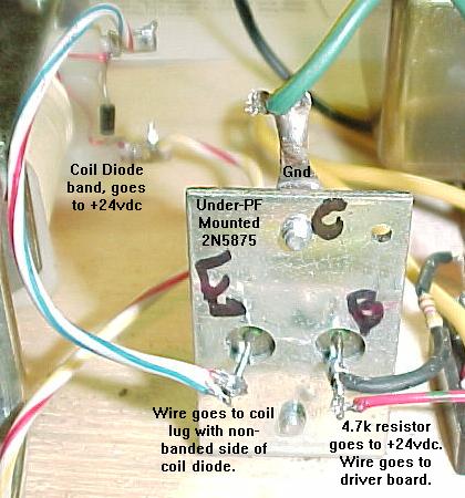
Anything less than 2 ohms and next remove the GROUND wire (the wire connecting to the non-banded diode coil lug), and retest the coil. If the coil resistance is no longer low, the driver board has a bad driving transistor for this coil (replace the under-PF transistor {if used}, driver board transistor, and pre-driver transistor). If the coil resistance is still low, cut the diode off the coil and re-test the coil. If the coil resistance is normal, the diode was bad (install a new 1N4004 diode). If the coil resistance is still low, the coil itself is bad. Replace the coil with a new one, and make sure there is a 1N4004 diode installed across the coil's lugs. Remember when reconnecting the wires to the coil that the power wire (usually two wires or thicker wires) goes to the coil's lug with the BANDED side of the diode attached. The thinner wire is the coil's return path to ground via the driver transistor and attaches to the coil lug with the non-banded side of the diode attached. If a low resistance coil is found, also suspect the associated driver board (or under-playfield mounted transistor if used) as bad. A low resistance coil is a red flag, a warning, that there may be problems on the driver board or with an under-playfield mounted driver transistor. Actually with System1 games, if a low resistance coil is found, I can pretty much guarantee that you will need to (should) replace of course the coil and coil diode, but also all the silicon devices in its ground path (under-playfield transistor {if used}, driver transistor on driver board, and any pre-driver transistor). I would also check the 74175 chip on the driver board (using a DMM set to diode setting), which drives the transistors, if any of the driver transistors were bad/replaced. See the Locked-on or Not Working Coil section of this document for more info.
2b. Before Powering On: The Power Train and the Power Supply (Repair/Upgrade)
The bottom panel (lower cabinet) is where the power all starts. The line cord comes into the game and goes to line filter. Next it goes to a line fuse (an an outlet plug), and then to the pair of transformers. Not Gottlieb does not use a MOV on the line filter (unlike Bally and Williams), so there is no surge protection in system1 games. The two transformers convert the 120 volts AC input to other voltages needed for the game. The large transformer outputs power for the solenoids (24 volts), general illumination light power (6.3 volts), and CPU controlled light power (6 volts). The small transformer outputs the main score display voltage (60 volts), the computer board voltage (12 volts which ultimately ends up as +5 volts), and the score display offset/reference voltages (8 and 4 volts).
After the power is converted from AC to DC via these three bridge rectifiers, it goes through bottom panel mounted fuses. Also the voltages that don't get converted to DC on the bottom panel also go through fuses on the bottom panel: There are other sys1 fuses beside the bottom board fuses, all mounted under the playfield. There is usually a fuse for the pop bumpers and other major coil items like drop target reset banks. My advice for fuses is simple: test EVERY fuse in the game by removing it and using a DMM (digital multi-meter) set to continuity. Don't try and give fuses a visual test! And I highly recommend removing the fuse from the fuse holder for testing, as this will show a fuse that is cracked or a fuse holder that is bad (and there are far less "false reading" testing a fuse out of circuit.) Obviously this is all done with the power off. Note many under the playfield fuses will not have their fuse value stated with a label. Many fuses will, but others will not (or the label fell off). For this reason it's a good idea to get a game manual. Do NOT over fuse! If it says "2 amp slow-blow", then that's what you should use. The fuses are there for a reason, to be the "weakest link". If over-fused, much more expensive items become the weakest link (like driver transistors and/or coils). So use the correct fuses.
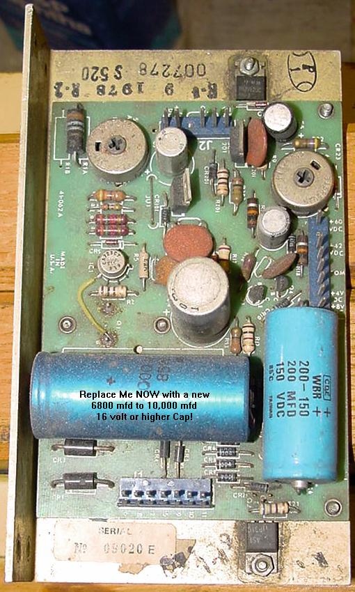
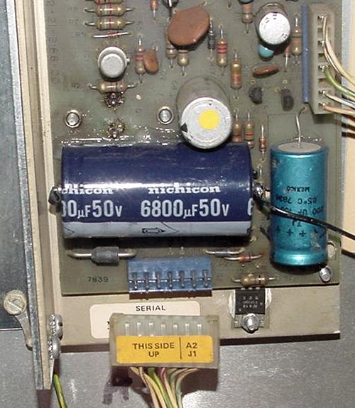
If a bad bridge is found, replace it with a new 35 amp 400 volt bridge with lugs. These are inexpensive and easy to get from a variety of electronic parts houses. An interesting note on the system1 power train bottom board - there is NO bridge rectifier for the 5/12 volt power. This is instead handled by the power supply board itself using a pair of 3 amp (3a100 or 1n5401) CR1/CR2 diodes. That means the +5/12 volts DC is only half-wave rectified and not full wave rectified. In addition the filter cap is only 2900 mfd. You would think this would provide a rather rippled +5/12 volts (which it does). For this reason you will need to replace the 2900 mfd power supply cap C1 with higher 6800 to 10,000 mfd version. This "problem" was dramatically improved with Gottlieb's later system80 games, where a full wave bridge rectifier was added to the bottom board for the 5/12 volts, and its filter capacitor was increases in MFD rating.
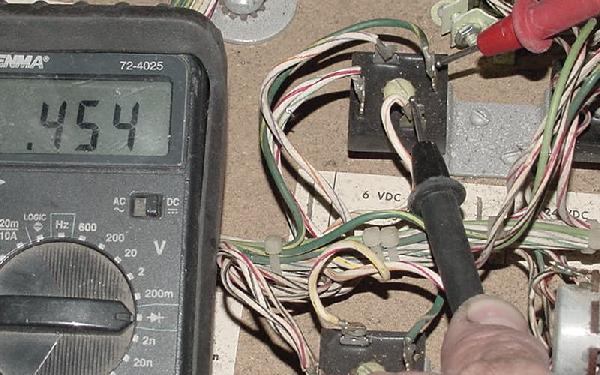
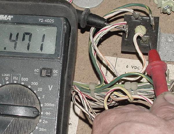
First is the Tilt "T" relay, which pulls in when the game is tilted. When energized at a tilt, this turns on the "tilt" light in the backbox, turns off the GI (general illumination) lights on the playfield, and turns off the power to all the coils on the playfield. If a ball is tilted during play, the ball will immediately drain (since there's no flipper or coil power). Once the ball hits the outhole switch, the CPU board will de-energize the Tilt relay, and the game continues.
As a diagnosing feature, with the game on and in "attract" mode (ready to take money and start a game), the Game Over "Q" relay can be manually held in (assuming your careful and don't knock the relay's activation plate off it's mounting pivot point). This will turn all the power on to the flippers, pop bumpers, slingshots without having to start a game. This is handy when adjusting and testing these devices.
Slam Switch (Coin Door) and Tilt Switches.
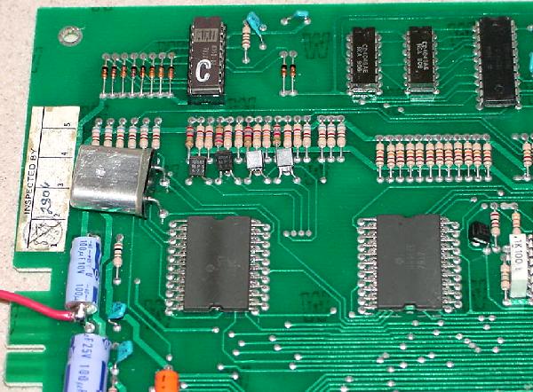
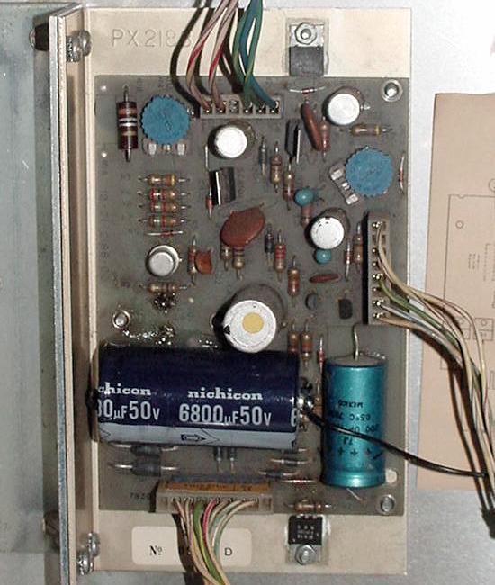
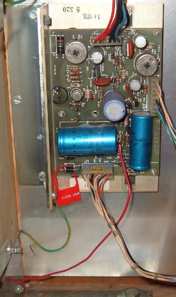
The Gottlieb System 1 power supply is a fairly robust device. But it certainly is not perfect. Heck it's not easy to work on either. In order to get to the solder side of the board (to remove any suspect components), the power supply must be "taken apart". This means removing four corner machine screws, then two machine screws used as heat sink screws for the outside edge TIP31's, remove two more machine screws for the Q1 transistor, and then desoldering the Q1 transistor. Wow that's a lot of work! And then after you think it's all fixed, you have to at least solder the Q1 transistor back and test the board. If you did well, then re-assemble the whole thing. It's a fair amount work. This is why many people just spent the $70 and buy the new replacment Rottendog Amusements power supply (which by the way is a good product) or the new Great Plains Electronics (GPE) system1 power supply (again, another great product). One problem with power supply is the -12 volts. If this supply is missing (it feeds only to the CPU board), the system1 game will power on with all the coils and most of the CPU controlled lamps "locked on". This is definately a bad thing, but should be kept in mind. Another problem is the +5 volt DC rectifying transistor Q1, which makes the whole board to get quite warm because it is attached to Q1's heatsink. After about 30 to 60 minutes, the entire power supply "L" aluminum frame (which is the heat sink for Q1, and which the entire power supply board is mounted) gets quite warm. This eventually causes the large C1 +5/12 volt filter capacitor (replace with 6800 to 10,000 mfd 20 volts) to dry out. This can cause strange problems and game lockups, or even damage to the CPU board. Sometimes even the Q1 transistor can fail. The original PMD12K40 transistor is hard to find, but if can be replaced with a 2N6057 or 2N6059. There is also another large filter capacitor at C6 (200 mfd 150 volts) used for filtering the score display voltage. When this cap dries out this causes the displays to flicker or go dim. Another common problem are the two trimmer potentiometers begin to fail because of dust, causing overvoltage or other problems. The trimmers can be cleaned with contact cleaner or preferably replace them with new ones. There are two pots, R4 to adjust the +5 volts (1k ohms) and another R16 (1k ohms) to adjust the +60 volts for the score displays. Rectifier diodes CR1 and CR2 (1N5401 3amp 100v) are underrated too. It is good to replace those with at least 4A diodes.
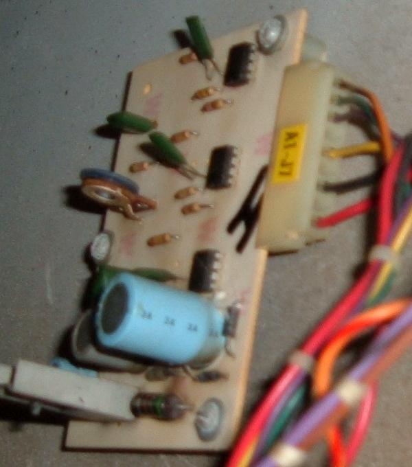
J1 Power Supply Connector Warning.
Replace the Power Supply's C1 5/12 volt Filter Cap NOW.
When replacing this capacitor it is NOT necessary to take the whole power supply apart! Just cut of the old capacitor off the power supply board, leaving the old cap leads as long as possible. The new filter capacitor will no doubt be much smaller (isn't everything made smaller today?), so just tie the new capacitor to the old cap's leads. The reason for this is simple - taking apart an original system1 power supply is a lot of work.
The stock Gottlieb System 1 CPU board requires -12 volts DC for the six spider chips to work. If an otherwise working game is powered on with the -12 volts missing (due to a bad power supply or bad connectors), all the CPU controlled coils will lock-on (and most of the CPU driven lamps), and the game will not boot. Obviously this needs to be fixed before proceeding.
There are two transformers in the bottom panel of a system1 game. The large transformer (C-17924) powers the coils, General Illumination, and CPU controlled lamp voltages. This transformer is very robust and seemingly never fails. The small transformer (B-17921) powers the logic voltages (ultimately 5/-12 volts), and all voltages for the score displays (69 volts AC and the reference voltages). Unfortunately this small transformer is fragile, especially the 69 volt score display windings. I have seen this transformer fail. The System 1 power supply has several main power blocks. Treat and test each block independently. There
Replace Power Supply Capacitor C1 Now!
Score Display Flicker.
Before powering the game up, it's good to know if the power supply (in its current state) works. Here is a good way to test a System1 power supply. This is a good generalized way to "bring her up", without smoke and fire.
Unregulated voltages (42/60 volts) can be higher than expected. For example, seeing 48 volts for the 42 volts test point, or 8.6 volts for the 8 volt test point are all Ok. Also 65 volts for the 60 volts is Ok, but there is a trim pot to adjust that voltage too. Regulated voltages like +5 volts should be in the 5.0 to 5.15 volt range (there is a trim pot to adjust the +5 volts). Also the -12 volts should be -11.9 to -12.1 volts.
Power Supply Test, Step Two: These steps makes sure that the +5 volts and -12 volts are not dragged down by the CPU board, or the connector going from the power supply to the CPU board. If +5 or -12 volts goes down, try adjusting the power supply trim pot. If voltage is below 4.8 volts, this will need to be fixed.
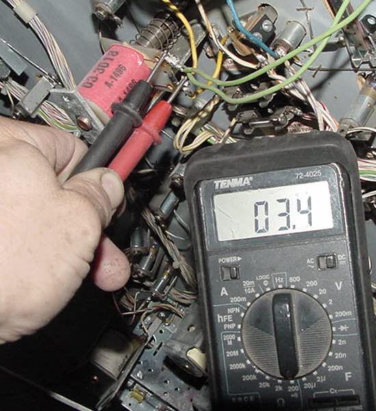
Power Supply Test, Step Three: If 60 volts and/or 42 volts are now missing, first check the four 1N4004 diodes on the power supply board. Using a DMM set to diode function, they should read .4 to .6 volts in one direction, and null voltage in the other. There could also be a shorted score display! Hopefully this is not the case, as a shorted display can easily take out the 7448 chips on the CPU board. Replace the 60 volt fuse in the bottom panel (it may or may not have blown!), and disconnect all but ONE of the score display connectors. Power the game on and check for 42 and 60 volts. Repeat this, adding one score display connector at a time, until the offending score display is found. Warning: only attach connectors with the power OFF.
The +5 volt transistor Q1 (PMD12K40 or 2N6059) makes the whole power supply board to get quite warm. This eventually causes the filter capacitors to dry out. A dried out C1 capacitor in +5/-12 volt circuit can cause strange problems and game lockups. Improper filtering of 60 volt display voltage by cap C6 (200 mfd 150 volts) can cause the score displays to flicker or go dim. In addition, the Q1 transistor can get so hot that it creates cold solder joints on other power supply components. Sometimes even the 5 volt transistor Q1 can fail. The original PMD12K40 transistor is hard to find, but a common replacement is the 2N6057 or 2N6059. This is a 60 volt, 8 amp NPN darlington. After years, also the trimmer potentiometers begin to fail because of dust, causing overvoltage protection to trip or other problems. The trimmers should be replaced with new ones. Rectifier diodes CR1 and CR2 are underrated too, and it's good to replace those with at least 4A diodes. Note the IC1 power supply part is a UA723CL, which is round metal cased version of the LM723 DIP package.
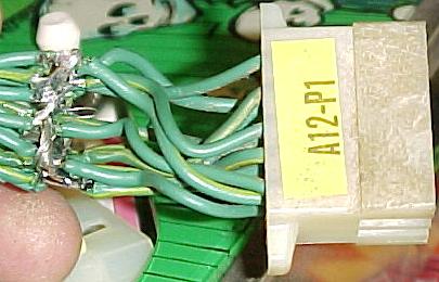
Power Supply Connector A2-P1.
Power Supply tips and fixes.
CPU Board Over-voltages.
Testing a Bridge Rectifier. To test a bridge rectifier, do this:
Replacing a Bridge Rectifier.
2c. Battery Replacement/Corrosion (CPU board Reset/Clock Circuits)
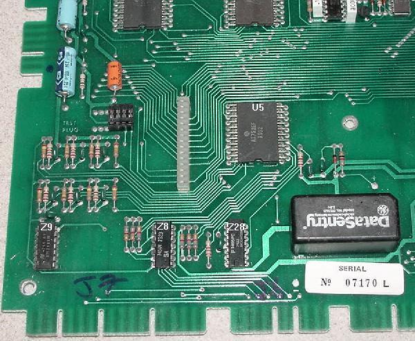
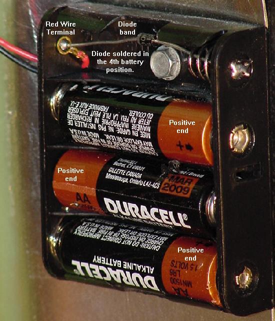
This fix is mandatory. All Gottlieb System1 boards use a recharagable "DataSentry" or AA nicad 3.6 volt battery. When these batteries don't get used regularly, they can leak the alkaline potassium hydroxide and volatile gases that destroy the CPU board components and connectors. Removal of 20+ year old rechargable battery is mandatory!
New Battery
Memory Back-Up Capacitors. Back-up capacitors are about the size of a stack of nickels, and Jameco (800-831-4242) sells 1 Farad memory caps, part# 142957. Remember CPU board memory "save" duration has to do with the exact memory brand on the CPU board, its age, and its exact manufacturing specs. Some memory chips have different power consumption rates, hence varying results can be seen with memory backup caps. Some CPU boards will maintain their memory for months with a backup cap, and others may only last a week. "Your mileage may vary" is probably a good statement about memory backup capacitors. When installing back-up capacitors, the minus and positive leads are often not labeled on the cap. There was only a black line on the cap to designate the negative lead (the CPU board is labeled; the positive hole has a "+" next to it). If the installed memory cap doesn't seem to work (and it was installed correctly), check the issolation diode CR26 (1N4148) using the diode function of a DMM. Its job is to make sure the cap/battery doesn't try and power the entire CPU board when the game is off (this would drain the cap/battery quickly).
Be Sure to Zero Out the Game's Audit Memory. To zero out the audit memory, turn the game on, and press the white diagnostic button inside the coin door. This will show "0" in the credit display, and the audit information in all the score displays. To zero out this memory position, press the black push button mounted on the CPU board, and the score displays should all go to "000000". Press the coin door diagnostic button once to advance to the next audit number, and again zero this out using the CPU board push button. Repeat this for audits 0 to 10. Press the coin door diagnostic button again, and then exit the audits by either powering the game off, or by opening the slam switch (or closing a tilt switch). This process will clear the game's audit memory.
Removing the Old Battery and Fixing Corrosion.
2d. Ground Problem Fixes
The Gottlieb Grounding Problem. First there is the problem with ground between *cabinet* ground, and circuit board ground. John Robertson documented this problem back in 1987. There is a single ground connection between the cabinet ground and circuit board ground on the power supply. If this single connection has resistance (which is common on older games), problems occur. This resistance, with the current drawn by the Driver board through the power supply, causes a voltage shift in the power supply's ground line. If the voltage shift get up to .5 volts relative to the cabinet ground, the solenoid driver transistors are no longer biased off, and start to conduct. This can cause playfield coils to "lock on" and burn, damaging the coil and its associated driver transistor. This single problem made many people think Gottlieb games were "unreliable". Mandatory Ground Modifications Steps.
At this point, the mandatory grounding modifications are done.
2e. Connector Pin Replacement - Mandatory
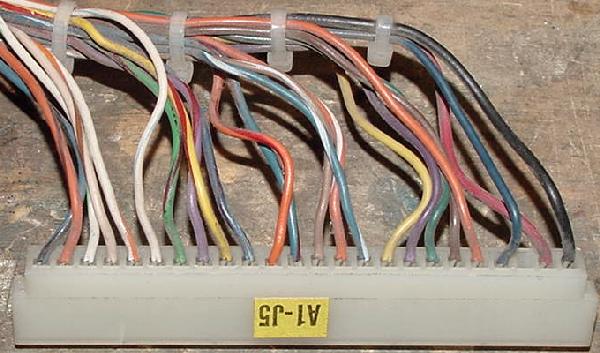
Connectors, Battery Corrosion, Vibration & Corrosion. These card edge connectors are rated for 25 "cycles" - that is 25 removal-installs. Over the life of a 20+ year old System1 game, certainly this life span has been exceeded. Combine that with battery corrosion problems and vibration from game play, and it's obvious that any Gottlieb System1 game will REQUIRE all the main connectors to be re-pined. If you want your System1 game to work reliably, YOU MUST RE-PIN ALL THE CARD EDGE CONNECTORS. If there are battery corrosion problems, these card edge connectors just magnify the problem (and sometimes allow the leaking battery electrolyte to travel thru the connectors to other boards!) If there is any battery corrosion on the circuit board card-edge fingers, this MUST be removed before any other connector work is done. If corrosion is visible on the board, clean the edge fingers by lightly sanding the corrosion with 220 grit sandpaper to remove it, revealing the copper plating. After the corrosion is removed, wash the circuit board in a 50/50 mix of white vinegar and water. Use an old toothbrush to wash the board with the vinegar mix. Then rinse the board with clean water. Finally rinse the board with alcohol, and allow it to air dry. If the board's connector fingers were sanded, use a soldering iron and some rosin flux to re-tint the connector fingers with solder. Heat the finger, apply some new solder, then quickly wipe the solder off the finger with a rag. This should leave a "tint" of solder on the copper finger.
Connectors are numbered in this fashion: the first "A" letter/number combination denotes which board the connector belongs. That is, A1 is the CPU board, A3 is the driver board, etc. After the board designation, the "J" letter/number combination is the actually connector number for that board. So "A1-J3" is board A1's (CPU board) J3 connector (note some Gottlieb documentation does not put a "dash" between the board and connector numbers). Below are a list of "A" numbers (applies to most System1 games): Here's a summary of the CPU board connectors. The connectors with a "*" next to it are the ones most often damaged by battery corrosion or vibration and need to be replaced most often.
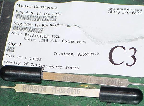
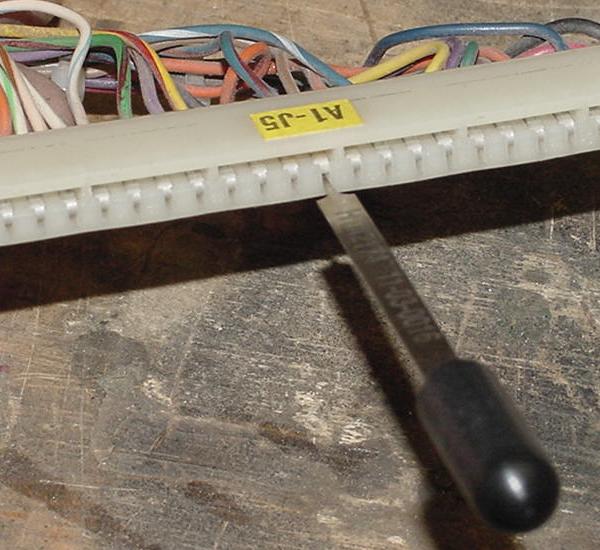
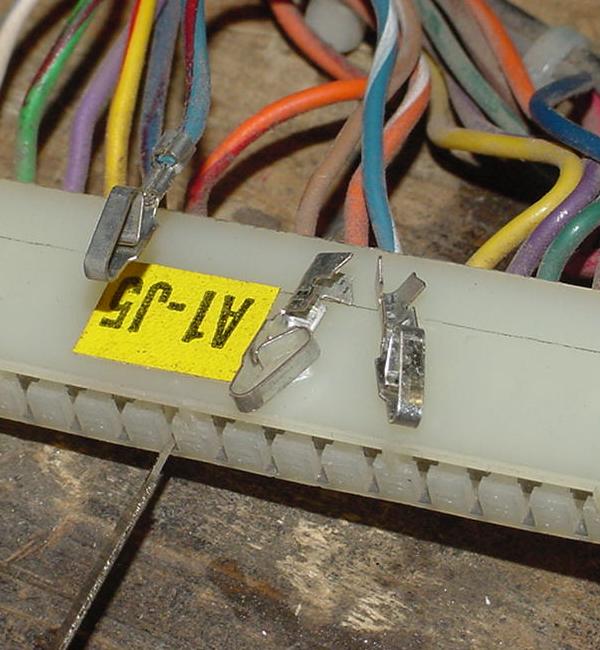
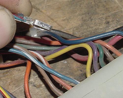
Replacing the Connector Pins. Parts and Tools needed: Connector (terminal) pins will be required. Molex connector pins are somewhat difficult to order, as there are so many different varieties. Note the "chain" variety are not wanted. The chained variety are designed for high-speed installation machines, not single use. Purchase only phosphor-bronze tin plated pins (do not use gold pins).
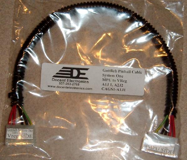
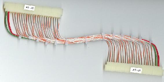
This single sided connector harness often has corroded pins because the CPU side of the connector is near the battery. If the harness is missing, a new replacement can be purchased from Docent Electronics (937-253-2763).
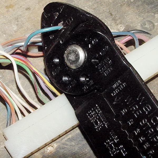
Crimp-On Connector Pin Replacement Instructions.
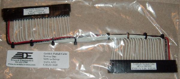
Steve Kulpa stevekulpa@yahoo.com and Docent Electronics docentelectronics.com sell brand new connector harness for the (often missing or damaged) power supply to MPU board connector, and MPU to driver board connector. Contact them for details, but the cost is excellent. They uses tin plated crimped pins, trifurcon for the header connector on the power supply, and 22 awg wire for signals and 18 awg wire for power lines.
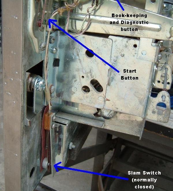
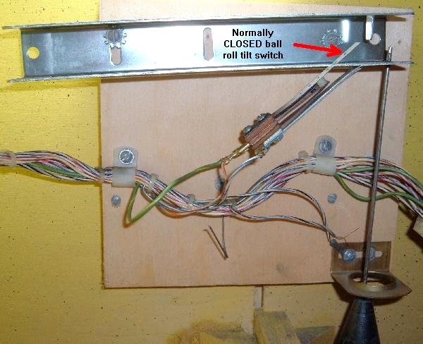
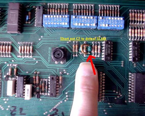
2f. Permanently Defeating the Slam Switch. Gottlieb used two slam switches in their pinball games and BOTH must be CLOSED or the game will not function. If you turn the game on and the displays come on IMMEDIATELY with all zeros (no five second delay and no relay "Click-Click"), this usually indicates one of the slam switches are open. If either of the two slam switches are open, the CPU board will *not* boot, and a game can not be started. Remember the normal System1 boot sequence: power-on, score displays dark, after 5 seconds the under playfield relays "click" and the score displays come on. If this 5 second boot-up delay is not seen, this is often because a slam switch is open. Or the CPU board has connector problems, usually due to battery corrosion at the J6 connector, which goes to the slam switches. There is one slam switch on inside front door around the lock, and one at the ball roll assembly at the left inside cabinet. Both these must be Normally Closed or the game will turn on the score display instantly with all zeros (no normal 5 second boot-up delay). Also you may see the score displays showing a wave like this "O0O0O0" then "0O0O0O" right to left. Again this shows a slam switch is open. Note the Tilt switch and the Slam switch are different! The Tilt switches (like the pendulum tilt, right below the ball roll assembly inside the cabinet) are Normally Open. There is also another weighted tilt switch mounted under the playfield. These tilt switches should be OPEN, where the two Slam switches are CLOSED. This is confusing because, for example, inside the cabinet at the left is the tilt pendulum which is open, and a slam switch on the ball roll right above it is closed. Because the slam switches go thru connectors and a lot or wiring to get to the switches, it is best to defeat the slam switches entirely. This can be done on the MPU board: short to ground the junction of R12 and C2 (or just run a jumper around capacitor C2, shorting its two legs).
|
|
3a. Fixing the CPU board.
Initial CPU Checking. Second, is there 4.95 to 5.2 volts DC at the CPU board? Best place to check for this is at the C16 capacitor (top most cap next to the the J1 power connector). Is there -12 volts DC at the CPU board? Best place to check for this is at the C17 capacitor (right below the C16 cap) next to the J1 power connector. The machine will absolutely not boot without +5 and -12 volts. Assuming the above voltages are correct, next check the score displays. Do they come on right at power-on and "strobe"? If so, there is a problem with the normally closed Slam switch. The CPU board should be modified so the useless Slam switch is not an issue (see here for details on that). Last do the score displays come on after the game is powered on for 5 seconds? They should, as this is the normal system1 boot sequence. If they don't, and then the CPU board is indeed "dead". If the CPU board turns on the score displays after 5 seconds of power, that is a good sign that the board is at least trying to boot. Also set the CPU board DIP switch as follows:
Booting the CPU board on the Workbench.
Another perhaps easier way to connect the voltage from the computer power supply to the CPU board is using the C16 (top most) and C17 (below C16) capacitors next to the J1 power connector:
Now the next problem to overcome are the score displays, or the lack of score displays. Since we can't use score displays on the workbench, we need some way to tell if the CPU board is "booting". When mounted in a game this is easy, as we turn the power on, wait 5 seconds, and then the score display should turn on (indicating a proper boot sequence). But on the workbench we can't do this.
Dead CPU: Next Steps.
Measure TC1 pin 14 and power the CPU on. It should show immediately at power on -12 volts. This will rapidly changie into +5 volts after about half a second. This is the RESET signal. Another place to check the Reset is at chip Z2 pins 7,9. (both should go high to 5 volts after about one second of power-on). If the reset is not working and does not change to +5 volts, it is best to replace the Q5 and Q6 (MPS-A70) in the reset circuitry. If the reset is still not going from -12 to +5 volts, change chip Z2 (4528 CMOS). Still not working, check or replace caps C31 and C32 (.1 mfd, and these do sometimes fail). Note that the "Reset" button on the CPU board has nothing to do with this Reset signal (it is only used to reset bookkeeping values).
Clock Circuit. The next thing we check are the clock signals. The clock circuit provides the timing the CPU chip needs to execute. This is provided by the CPU board cyrstal and the U1 spider chip. Check TC2 pins 11,12 using an o'scope or a logical probe, and there should be pulsing signals. Also check both legs of the cyrstal, and the same pulsing should be seen on both legs. If an o'scope is not available, use a DMM set to DC volts. This should show 2.8 volts at TC2 pin11 and 2.9 volts at TC2 pin12. The top leg of the crystal should show .3 volts, and the bottom leg should show .9 volts. If there are no clock pulses, there is a problem with the Rockwell U1 spider chip, and the story ends here (as the spider chips are no longer available). The only choice is to buy a new NiWumpf or Pascal CPU board. There is a chance the crystal (above the J1 power connector) is bad, but that is unlikely (but it does happen). Crystal Y1 is a 3.579 MHz crystal. Address/Data Line Activity. Now that we have a reset and clock circuit, check the address and data lines for activity. This is done at TC1 pins 1-13. Use an o'scope or logic probe looking for pulsing lines. If there's no pulsing, the Rockwell spider chip(s) are bad, and again the story ends here (buy a NiWumpf or Pascal CPU board). If pulsing is seen at TC1 pins 1-13, then it's time to move to the next step.
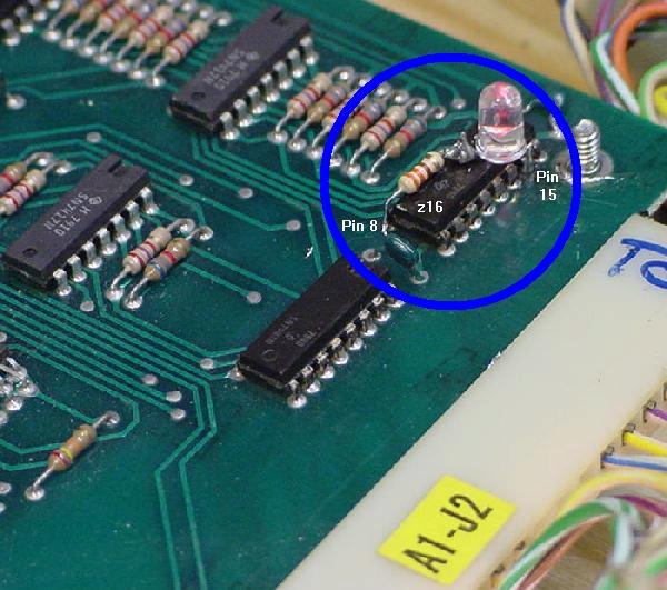
Score display LED On? Testing the Input/Output Buffer and Spider Chips. In order to check the buffer chips, we will activate the buffer inputs, and see if there is a corresponding response at the buffer outputs. The buffers chips are Z29 (7405) and Z27 (74H21), both right below the DIP switch. Also Z9 (7405) and Z8 (7404), both at the bottom left of the CPU board. Use an alligator clip connected to ground to activate the buffer inputs, which will control the buffer output pins. A logic probe is best for checking the output, but a DMM set to DC volts can be used.
Ground Z29 pin 5 (input) and check pin 6 (output). Ground Z29 pin 11 (input) and check pin 10 (output). Ground Z29 pin 9 (input) and check pin 8 (output). All outputs should show +5 volts.
Ground Z27 pin 1 (input) and check pin 2 (output).
Switch Matrix Returns:
Switch Matrix Returns: If any input is grounded and it's associate output does not respond (by going to +5 volts), the chip is bad.
Z8 pin 1/2 = Strobe0: both pins pulsing. Z8 pin 3/4 = Strobe1: both pins pulsing. Z8 pin 5/6 = Strobe2: both pins pulsing. Z8 pin 9/8 = Strobe3: both pins pulsing. Z8 pin 11/10 = Strobe4: both pins pulsing. Z8 pin 13/12 = Strobe5: both pins pulsing (not used in any system1 games).
Now we can test the solenoid buffer chips at Z6 and Z7 (7417). The 7417 chips at Z6 (located just above connector J5) and Z7 (to the right of Z6). The U4 spider chip sends signals to the Z6/Z7 buffers, which then signal the driver board transistors at Q25-Q32 for the CPU controlled coils. With the CPU board power on, attach an alligator clip to +5 volts (the positive/upper lead of capacitor C16 on the CPU board). Then touch the Z6 input pins (one at a time) with +5 volts, and watch the output pin:
Z6 pin 3 (input) and check pin 4 (output) Z6 pin 5 (input) and check pin 6 (output) Z6 pin 9 (input) and check pin 8 (output) Z6 pin 11 (input) and check pin 10 (output) Z6 pin 13 (input) and check pin 12 (output)
Z7 pin 1 (input) and check pin 2 (output) So once the solenoid buffer chips are tested, we need to have some way to test the U4 spider chip (which sends solenoid signals to Z6/Z7). It is impossible to control all the outputs of U4 on the bench, but if we control some of them. If the U4 works for the ones we can control, it will probably be OK for the rest. We can use the machine's "play-a-tune" feature when a coin switch is activated (make sure DIP switch 23 is "on"). If we can simulate a coin switch closure, the U4 spider chip will send signals to the Z6 chip, activating the three chime coils (or sound board triggers). We can see this with a logic probe at the Z6 chip. To simulate a coin switch closure, Use a jumper wire and connect one end to chip Z8 pin 4. With the other end momentarily touch Z9 pin 1. This simulates a coin drop by momentarily touching switch matrix strobe1 to return0. Using a logic probe, check the following Z6 solenoid buffer chip pins which the U4 spider chip toggles:
Z6 pin 9 (hundred point chime). Z6 pin 11 (thousand point chime). You should see the above pins go high as the coin switch closure is simulated. If any one of the above pins do not go high, the U4 spider chip is bad. Since there is no replacement available for the U4, the CPU board is junk and must be replaced. The only thing not tested on the bench is the U6 spider chip and Z16/Z17 7448 chips that control the score displays. This spider rarely fails, and it is very easy to test the displays using the game's built-in diagnostics. So there really is no need to do this on the workbench.
CPU Considerations (Spider chips, etc).
Here's a summary of the spider chips: * Note that spider chips U4 or U5 contain the game operating system ROM, and must be of the same revision. These are the two spiders that fail the most. The revision levels that work together are:
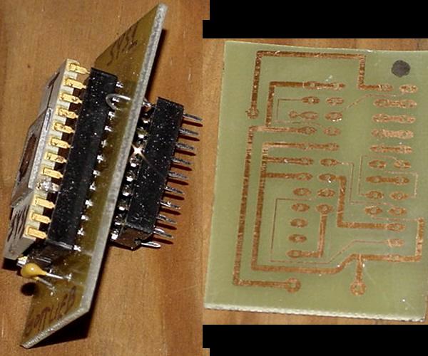
Socketing Spider Chips. To do this, buy some SIP (single inline pin) machine pin sockets, and solder them into the board. This way the spider can be pluged into the SIP sockets. As a note of caution, it's best to "double up" the SIP sockets (as shown in the picture below). This is done for two reasons. First so the spider legs (which are somewhat wide) don't stretch the SIPs soldered into the board. That is, if the spider legs cause problems, they will ruin the easy-to-remove SIPs on the legs, not the SIPs soldered into the CPU board. The second reason to "double up" the SIPs is to aid in the installation of the spider chip into the board-mounted SIPs. Aligning all the spider chip pins is tricky. But if extra SIPs are installed on the spider chip first, installation of the spider chip into the board-mounted SIPs is *much* easier.
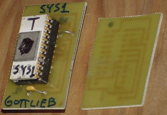
3b. Game ROMs, PROMs, EPROMs and Test PROM. The game PROM at Z23 is a 18 pin PROM which contains the game specific rule computer code for the CPU board. This bipolar PROM is not duplicatable in its native form, as blank PROMs are long gone. Also nearly long gone is any sort of PROM programmer that would program a blank (if one could be found). Add to this that the bipolar PROM at Z23 is often bad (it runs very hot, even when working properely), and this becomes a problem for a System1 CPU board. Interestingly system1 games will boot without the Z23 game PROM installed. Because the majority of the system code is inside the "spider" chips, the game PROM is not needed to boot a system1 CPU board. Diagnostics/audit can even be run with no Z23 game PROM installed. The game can be coined up. But if a game is started with no Z23 Game PROM installed, the start-up sounds will play, and then the game will lock up.
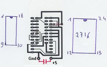
Using a 2716 EPROM for the Game PROM at Z23. Ni-wumph's main game 27256 EPROM and board manual is available directly from Niwumpf's support web page. The Niwumph EPROM image is also available here and the manaul here for convenience. Schematics for Niwumpf are also available here, here, here.
Making a 2716 EPROM Adaptor for the Game PROM at Z23.
Gottlieb System1 Test PROM "T".
Using the System1 Test PROM. To access the Test PROM start a game (no credits are needed, but you can add credits if you want, and the coin-up tune will play). As soon as a game is started the game start-up sounds will play (10,100,1000 point sounds or chimes coils 3,4,5) and then the outhole (coil1), the knocker (coil2), the outhole (again), and three game specific coils 6,7,8. While this is happening the Game Over relay will pull in for about two seconds and then release. All the coil energizing happens very fast at game start (the only coil that does not pull in is the Tilt relay). Also all 36 of the CPU controlled lights will turn on for about two seconds and then turn off. The CPU lights do this (starting with lamp #01 to lamp #36) in a quick progression. At this point the game's playfield switches becomes the Test PROM's input. All game switches (except for the two coin chute and credit button) have a test function. All the CPU controlled lamps should be off. Hitting a playfield switch should toggle a CPU controlled lamp on or off, and/or fire a solenoid. If the game has all 40 switches wired, all 36 CPU controlled lamps can be turned on (assuming the game uses all 36 lamps). You will need the game manual to know how a playfield is wired for this excercise, because you will need to know where each switch number is found on the playfield to determine what it controls. The slam switch or outhole switch will exit the "game" (test) mode and go back to attract mode.
3c. Built-in Diagnostics/Bookkeeping Inside the coin door there is a large white momentary switch that is known as the "play/test" button. Press this button to access the game audits and test modes. After the button is pressed, it takes about one second and then the audit number "0" will appear in the ball/credit display, signifying the first audit value. The value for the audit will appear in the score displays. As the test button is pressed, the ball/credit display will increment a number 0 to 13 indicating the test/audit number. If any audit number (0-10) needs to be cleared, press the CPU board mounted black "reset" button to clear the audit value. To exit the test mode, either open the Slam switch or close a Tilt switch. Note on the high score level replay values. Setting a "zero" at high score level means the level is not in use. But this does not apply to the High Game to Date score level (the zero does not disable this). While in audit/diagnostic mode, the Q (game over) relay will be energized. This means the flippers and pop bumpers and slingshots (non-CPU controlled) coils should work while the game is in audits.
Audits: Diagnostics:
Diagnostics. Another problem with the lamp test is lamps L3 and L4 (Q3 and Q4). On many System1 games, these two MPS-U45 transistors are used for the High Score to Date and Shoot Again lamps. Hence these two lamps (L3/L4) are tested in the lamp test (on for five seconds upon entering test #13). But on some System1 games Q3 and Q4 are used as pre-drivers to under-playfield mounted 2N5875 transistors. These in turn control a playfield solenoid. If this is the case, these two solenoids will energize for five seconds in the lamp test! Just keep that in mind. After the CPU controlled lamps are turned off, each CPU controlled solenoid is energized one at a time. Well not really all of the CPU controlled solenoids. For example, the T (Tilt) relay is not included in this test. Neither is the Q (Game Over) relay, which is already energized during the whole audit/test routine. But all the other ten solenoids (including three sounds/chimes) will be tested ONCE. Then the test moves to the switch matrix test. If there are no closed switches, after about 5 seconds the game will exit test #13 and go back to attract mode. If a closed switch is found, it will display in the ball/credit display. If you want to test a switch, do it now! Hurry up though. If no other switches are sensed as closed within a five second window, the game will exit the test mode and go back to attract mode. Also if you hold a switch closed, it takes about *two* seconds before that switch number appears in the ball/credit display! Talk about a slow CPU board. Overall the #11,#12,#13 Gottlieb System1 diagnostic tests are pretty lame. Especially compared to comparible Bally and Williams diagnostics of this era (1977-1980). Ideally it would be nice to flash all the CPU controlled playfield light on and off continually until the user wants to proceed. This can not be done with the System1 diagnostics. Also again it would be nice to keep running the coil test over and over, and to keep the game in switch test mode until the user wants to exit. Unfortunately these things can't be done with the stock System1 diagnostics. This makes finding bad CPU controlled lamps, coils, and playfield switches more difficult. Another method of testing lamps, coils and score displays is to use a NiWumpf CPU board. The testing routines in the NiWumpf board are *much* better than the stock Gottlieb System1 tests. For example, CPU lights can be continually cycled on and off. Same thing with coils (and the Game Over and Tilt relays are activated too!) And the NiWumpf display test also tests the 4-digit ball/credit display (which the stock Gottlieb test does not). So using the NiWumpf to test a driver board works very well. The NiWumpf switch test operates as it should and is very quick to display a closed switch (but unfortunately this test can not be used on a stock Gottlieb CPU board).
The Z23 Game PROM and Diagnostics.
Gottlieb Test PROM for Z23.
3d. Locked-on or Not Working Coils
In the case of a non-working or locked-on coil, first figure out if the coil is CPU controlled. Pop bumpers, slingshots and coin door lockout coils are *not* CPU controlled. All other coils are. Next figure out which driver board transistor(s) control the coil in question.
If many or all solenoids and CPU controlled lamps are constantly on or solenoids do not work at all, the problem could be missing -12 volts DC at CPU board. Of course without this voltage the game won't "boot" either. But check for -12 volts across CPU board cap C17 (below C16). If it is OK, the problem could be in the CPU board buffers Z6 and Z7 (7417) too (more on that later).
Step 2: Check the Coil Resistance.
Step 3: Check the Driver board to Coil Wiring (Connectors). Now move up to the backbox, and attach one end of an alligator clip jumper wire to ground. Touch the other end of the jumper wire momentarily to the metal tab of the controlling transistor. This should fire the coil. (Note on Q29/Q45 controlling transistor pair, ground only the metal tab of the larger Q45, as grounding the small Q29 will yield nothing). If the coil does not fire, suspect a bad connector on the bottom edge of the driver board (or a broken trace on the driver board). If the coil fires, time to move to the next step and test the transistors and controlling chips, eventually moving all the way back to the CPU board. Connectors are a huge problem on System1 games, don't overlook them. The connectors along the bottom edge of the driver board *and* the connector that runs between the driver board and/or CPU board could cause a coil to not work. See the Connector section for more information on how to replace System1 connectors.
NOTE 1: testing transistors with a DMM is only about 95% certain to work. The DMM is testing the transistors at "low load", which is unlike how the transistors will ultimately be used in the game! MPS-U45 transistors are particularly prone to testing good, but not working in the game. NOTE 2: Any transistor that tests "bad" should also have its playfield coil tested too as outlined here. If the driver board transistor(s) are replaced, but the playfield coil is burnt and has low resistance, it will immediately blow the freshly replaced driver board transistors.
Testing System1 Transistors with the Driver Board Removed.
MPS-U45 transistors (driver board locations Q1-Q4, Q29).
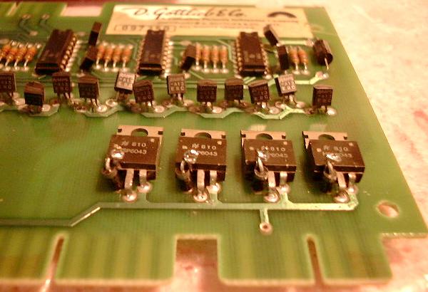
2N6043 or SE9300 transistors (driver board locations Q30-Q32, Q25-Q28). 2N3055 transistors (driver board Q45, large transistors with the huge metal case, pre-driven by Q29). This transistor is usually used for a drop target reset bank or other big coil usuage. This transistor tests the same in circuit and out of circuit.
2N5875/2N5879/2N5883 Playfield Mounted Transistors. Here's the list of System1 games that use under-playfield-mounted 2N5875 transistors:
The 74175 chip at Z1 is what controls the transistors for the Game-Over relay, Tilt relay and Q3/Q4 (if used to pre-drive an under-playfield mounted transistor). The rest of the 74175 chips are used for the CPU controlled lamps. These chips can be easily tested with a DMM set to the diode function and the game off. Best to do this with the driver board removed. The 74175 chip at Z1 can also be used to test the driver board transistors at Q1-Q4 (Q1=Game Over relay, Q2=Tilt relay, Q3/Q4=any under-the-playfield mounted transistors). With the game on, attach an alligator clip to +5 volts (the positive/upper lead of capacitor C1 on the driver board). Then touch the Z1 pins 2,7,10,15 with the other end of the alligator clip. This will tell the transistors Q1-Q4 to activate its relay (or coil or lamp). This is a good test to run if you are unsure if one of the Q1-Q4 transistors is really good. This test of course assumes that the coil/relay being driven is not locked-on.
7417 chip Test (CPU board locations Z6,Z7). With the game on, attach an alligator clip to +5 volts (the positive/upper lead of capacitor C16 on the CPU board). Then touch the Z6 pins 1-6 and pins 8-13 (note pin 7=gnd and pin 14=+5). Each pair of pins (for example Z6 pins 1,2) should fire its associated coil when attached to +5 volts. The same thing can be repeated for Z7 pins 1-4 (only). Refer to the above chart to see which Z6/Z7 pins control which driver board transistor/coil. If only one of the two pairs of pins activates the coil, the Z6 or Z7 chip is bad. If neither pin activates a coil, check the CPU to driver board connector and the driver board transistor. This test will tell the transistors Q25-Q32 to activate its coil. This test of course assumes that the coil being driven is not locked-on. If this test passes, yet a coil still does not work, then the problem is most likely the U4 spider chip (which sends the signal to Z6/Z7 to fire a coil). Unfortuantely the U4 spider chip is not available, and the CPU board must be replaced with a NiWumpf or Pascal CPU board.
Can a CPU board Problem cause a Non-Working Coil?
The Gottlieb System1 games also have several non-CPU controlled coils. These include the slingshot kickers and the pop bumpers. They are wired very similar to EM games, where the ball closes a playfield switch, which in turn connects powers the pop bumper or slingshot. There is a secondary switch which closes when the coil energizes that tells the CPU board to score points for the device. Note this is similar to what Gottlieb did on System80 slingshots, but dis-similar to system80 pop bumpers (which used an electronic pop bumper board to "one shot" the pop bumper coils). If a System1 pop bumper or slingshot "locks on" and stays energized, the reason for this is very simple; the playfield switch which controls the device is stuck closed. If the device does not work at all, start a game and check for power at both lugs of the coil in question. No power at either lug, check the solenoid fuse. Power at one lug and the coil is bad. No power at either lug check the T (Tilt) relay Normally Closed switch and the Q (Game Over) relay Normally Open switch.
Earlier Solenoid Driver Boards on Cleopatra, Sinbad, Joker Poker. Because of this, it is a good idea to check which driver board is installed in your game. Even if you have a later System1 game, check for these diodes (as the driver board could have been swapped at some point).
3e. Locked-on or Not Working CPU Controlled Feature Lamps
Semi-CPU Controlled Lamps. The 6.3 volts AC power for the Tilt lamp goes through a Normally Open switch on the Tilt relay. The Tilt relay is then controlled by the CPU board. If during game mode the machine is tilted, the Tilt relay energizes and stays energized until the current ball drains. While the Tilt relay is energized, this closes the switch to the Tilt lamp, turning the Tilt lamp on. Hence the semi-CPU control of the Tilt lamp. The Game-Over lamp works in a similar manner. The 6.3 volts AC for the Game-Over lamp goes through a Normally Closed switch on the Game-Over relay. The Game-Over relay is controlled by the CPU board. When a game is started, the Game-Over relay energizes for the duration of the game (enabling power to the flippers, etc.) This opens the Game-Over lamp switch, turning the Game-Over lamp off while a game is played. Hence the semi-CPU control of the Game-Over lamp.
CPU Controlled Lamps' Power.
If there is no power at the CPU controlled lamp sockets, check the 8 volt fuse in the bottom cabinet (5 amp slow-blow). If the fuse is good, also check the bridge rectifier closest to the copper ground strap. It is common for this bridge to go open or short (if shorted its fuse will blow immediately at power-on). If the bridge is suspected as bad, replace it with a new MB3502 or MB3504 lugged 35 amp 200 (or 400) volt bridge rectifier. If all the CPU controlled lamps are dim, the bridge is weak and should be replaced with a new lug-lead 35 amp 200 volt (3502) bridge. A suspect bridge can be tested. Use a DMM set to diode function and test the bridge:
The Driver Board and CPU Controlled Lamps. A single wire goes from each CPU controlled lamp socket back to the driver board, connecting to its related transistor. The driver transistor (MPS-A13 or MPS-U45) switches ground on through the 74175 chip to illuminate its respective lamp. Hence if any of these single wires are manually grounded with the game on, its respective lamp should light. This can be done easily by using an alligator test lead with one end connected to to copper ground strip on the game's bottom panel or any metal cabinet frame piece in the backbox. Then touch the other end of the test lead to the right-most leg of a MPS-U45 or MPS-A13 transistor (as facing the driver board installed in the backbox). This tests the connection from the driving transistor to the lamp socket (it does not however test the transistor). If the lamp does not light when grounding the transistor leg (and the bulb/socket are good), suspect a bad driver board connector or broken wire (or a bad bulb or light socket). Often lightly sanding the driver board's connector "fingers" can fix a non-working lamp. Or the connector pins may need to be replaced (very common). Note a good number of non-working lamp problems are related to connectors. If the .156" single sided Molex connectors at the driver board are in poor condition, this of course will mean a lamp will not work. Before attempting driver board repair, check all card edge connectors attaching to the driver board, and re-pin the connectors as needed. See the Connector section of this document for help with that. If grounding the right leg of any MPS-A13 transistor does light a CPU controlled lamp, but the lamp refused to workin in diagnostic or game mode, next test the transistor in question.
Each lamp is driven by a 74175 chip and a MPS-A13 or MPS-U45 transistor on the driver board. If a 74175 chip totally fails, it causes four lamps to stop working, and those lamps can either stay always on or off (depending on how the 74175 failed). If a driver transistor fails (which happens far more often than a failed chip), it affects only one lamp. A brightly lit lamp is a sign of a failed driver transistor. A non-working lamp is also a sign of a failed driver transistor (assuming the transistor leg grounding trick does light the lamp). Note the MPS-A13 transistors damage easily if the 8 volts driving the lamp gets shorted directly to its grounding wire with no load (no bulb), usually by a bad lamp or bad lamp socket.
MPS-A13 Transistor Test (driver board locations Q5-Q24, Q33-Q44).
MPS-U45 Transistor Test (driver board locations Q1-Q4, Q29).
74175 Chip Test (driver board locations Z1-Z9).
How do I know which Transistor Controls Which Lamp? With the game powered off, go to the driver board and examine the connectors along the bottom edge of the driver board. Find the wire color in question and make note of the connector and pin. Using a DMM set to continuity, put one lead of the DMM on the pin with the correct wire color. Then probe the RIGHT leg of each transistors on the driver board. When a continuity buzz is heard, the transistor controlling the lamp in question has been found. To double check you have found the correct transistor, power the game on. Now use an alligator test lead and connect one end to ground. Momentarily touch the other end of the alligator test lead to the RIGHT leg of the transistor. The CPU controlled lamp should light.
3f. Switches and the Switch Matrix
The System1 switch matrix consists of five strobe lines (Strobe0 to Strobe4) and eight return lines (Return0 to Return7). This makes for a total of 5x8 or 40 switches in any System1 game. The switches are numbers as such: 00-04, 10-14, 20-24, 30-34, 40-44, 50-54, 60-64, 70-74. The first five switches (return line #0, switch numbers 00 to 04) are consistent in all system1 games:
Two Switches Outside the Switch Matrix - Slam & Outhole. On the Ni-Wumpf board, there is no slam switch (it was completely removed from the circuit because of the problems it causes with stock Gottlieb System1 CPU boards). Also the Outhole switch is shown on the Ni-Wumpf switch test as switch number 15 (which is clearly outside of the 10-14 return1 row of switches). On the Gottlieb System1 switch test the outhole switch is shown as switch number 12 (which is clearly is not, but that's how the test shows it).
A Common Switch Matrix Problem.
CPU Board Switch Matrix Plugs.
This plug is used for the all important Slam switch and the coin, credit, tilt, and test switches.
Plug A1J7.
Shorting GI or Solenoid Voltage to the Switch Matrix. If any of these scenerios happen, a couple things can happen. Almost certainly the 7404 chip at Z8 (the strobe0-strobe4 buffer chip) can fail. Also the 7405 chip at Z9 (return0-return5 buffer) and Z28 (return6-return7 buffer) can also fail. This is not a huge deal as these chips are readily available. But behind the 7404/7405 chips is the irreplacable U5 (A1752CX) spider chip. If this chip fails, the CPU board is junk and can not be fixed, because this spider chip is no longer available and impossible to find. J.Robertson is currently testing a modification to the CPU board to to prevent the over voltage getting to the irreplaceable U5 spider. He has added clamping 1N4004 diodes to the circuit. These can be placed across the resistors R65-R72 with the band of the diode soldered to the +5VDC end of the resistor, and the non-band end to the other side of the resistor. Then on resistors R57-R62, connect the non-banded end of the diodes to the junction of the resistor and the trace leading to the IC, and the banded end to a convenient +5 volt point.
Switch Matrix Problems.
Z8 - 7404 (switch Strobes): If the logic probe shows pulsing just on the input side of the 7404 (first pin listed above) and not on the output pin, then the 7404 chip at Z8 is bad. If incorrect activity (no pulsing) is seen on the input side of the 7404 chip, then the U5 spider chip is bad. Z9/Z28 - 7405 (switch Returns):
3g. Score Display Problems and Fixes Warning! Do not remove or attach CPU connectors J2 and J3 (the score display connectors) with the game power on. Do not remove a score display with the game power on. Doing either of these with the power on will likely damage the CPU board score display driver chips, usually Z16-Z17 (digit control) and/or Z13-Z15 (ones control) and/or Z18-Z21 (digit selection). Sometimes the score display's UDN6116 chip blows too.
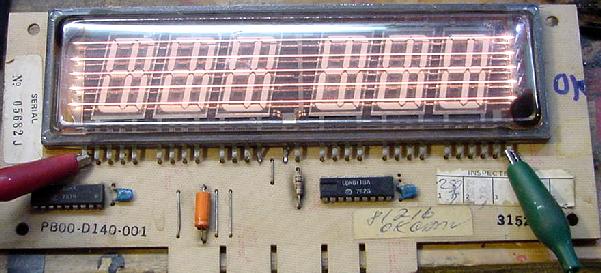
Introduction and What Controls What. The displays are controlled by CPU spider chip U6 and a few TTL chips. The 7-segment decoders Z16,Z17 (7448) control the digits for the displays. If the displayed numbers look strange then one of these chips is probably bad. Chip Z16 controls player 1/2 displays and the credit/ball display, while Z17 handles player 3/4 displays. There is also a circuit that makes number "1" to be shown with an extra eighth segment in the middle of the digit instead of the usual two right side segments. This is done with chips Z13/Z14/Z15 on the CPU board. Suspect those if there are problems in showing number "1". The displays are multiplexed, meaning one digit is display at a time. This digit selection signals come from CPU chips Z18-Z21. Finally there is a UDN6116 chip on the display board itself that controls the digits on the score display. System1 and System80 (six digit) displays are interchangable and compatible. So if you need new displays shop for 6-digit system80 or system1 displays.
The six digit blue Futaba score displays used on System1 and System80 games are identical and interchangable. But often the displays will fade over time, eventually not working at all. There may not be any problems with the display circuits themselves, but instead there may be oxidation on the display glass filiment wires. There is a trick to burn this oxidation off the filiment wires, making the displays work like brand new (there is a limited number of times you can do this though, the law of diminishing returns does apply).
WARNING: Do not leave the power to the display for more than 5 seconds, or you could burn a filiment wire ruining the display! Also do not use coil voltage to recharge the 4-digit ball/credit display. If you need to recharge a 4-digit ball/credit display, use 8 to 12 volts DC instead. I have even heard of some people using a 9 volt battery to do this.
3h. DIP switch settings.
There are three banks of eight DIP switches on the CPU board. They are used to set game pricing and other game parameters. These switches are consistent for all system1 games. The first eight switches control play pricing. There are four switches for each coin slot, so that the switches 1-4 control left side and switches 5-8 the right side coin slot. The other two DIP switch banks control game options. My suggestion is to set the CPU board DIP switch as follows to make repairing the game easier. After you have the game working, set the switches as desired.
Having the switches in these positions will make troubleshooting a bit easier and consistent from board to board.
3i. Backbox & Playfield General Illumination. Unlike most other pinball makers, general illumination lights (non-CPU controlled) are not a big problem in Gottlieb System1 games.
The other relay Q is the Game Over relay. It pulls in during game play and bookkeeping. It enables power to the playfield solenoids and flipper. The backbox "Game Over" and "Match" lights are also controlled by the Q relay. The third NC switch on this relay is a bit of a mystery - it disconnects the tilts switches in game over. Don't know why, maybe just a quick fix for a software problem? Or a trick to prevent players testing the sensitivity of tilt before starting a game? (more likely.)
3j. Sound board problems.
System1 Sounds.
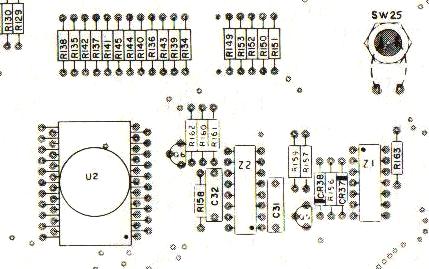
The +5 volts for the second generation sound board comes from an onboard 7805 regulator (center top of board) on games Totem and later. The ground connection is from two zinc plated mounting screws. These screws can corrode, causing the ground connection to be intermittent. Worse, the regulator output voltage can rise to +12 volts because of this bad ground. This can of course ruin the logic chips, and often the 6530 RIOT chip. The 6530 RIOT (RAM, input, output, timing) chip is no longer available and very hard and to find and expensive. And since the 6530 contains masked ROM code, it is unique for this board. So it is important to check and clean the 7805 regulator mounting hardware. Put some grease on the surfaces before reassembling, to prevent moisture causing any corrosion and blowing up the hard to get parts.
Substituting Chimes for the Sound Card.
3k. Flippers, RotoTargets, Etc.
Gottlieb lists rubber part numbers in their manuals, but does not indicate the actually sizes and types of rubber. So below is a list of the rubber parts and sizes.
3L. Miscellaneous Problems and Fixes
Problem: Can't add more than one credit to the game,
or bookkeeping memory appears to be blanked, or
replay scores cannot be set.
Problem: Game goes to "GAME OVER" during play for no apparent reason.
Problem:
On a Genie I have a display problem: the 1000s digit on player 1 & 3
slightly glow and makes it hard to read the proper number. I also noticed
that when a game is started and you have the flasing "0" for the player 1,
then the 1000s digit will also light up the same as the credit display.
Problem: While resetting the score levels stored in memory,
holding the credit button in fails to increment the score setting.
Problem: My game does strange things.
Problem: Coils or driver board transistors get very hot.
Problem: Game starts, gives ball to shooter and freezes.
Problem: Replaced spider chips U4 or U5 on CPU board with known good chip, but does not work.
Problem: Buck Rogers "thinks" it needs to score. Start a game, and it continuously
increments the 100s count score. The ball is
ejected, and the game starts counting up points. There are times when
this doesn't happen. But when the first score is made, i.e., the ball
going over a switch, then the scoring just keeps on going. Makes
for an intersting ball, but make the game useless.
Check ALL switch matrix inputs with a logic probe for a stuck switch, and NO switch
matrix inputs are sending anything to the MPU to tell it to start scoring.
Checked the output of the inverters (Z9 and Z28) to see if one
of them is sending something to U5. The inverters are working fine.
| |||||||||||||||||||||||||||||||||||||||||||||||||||||||||||||||||||||||||||||||||||||||||||||||||||||||||||||||||||||||||||||||||||||||||||||||||||||||||||||||||||||||||||||||||||||||||||||||||||||||||||||||||||||||||||||||||||||||||||||||||||||||||||||||||||||||||||||||||||||||||||||||||||||||||||||||||||||||||||||||||||||||||||||||||||||||||||||||||||||||||||||||||||||||||||||||
|
* Return to the Pin Fix-It Index * Return to Marvin's Marvelous Mechanical Museum |


