1a. Getting Started: Introduction
What is an "EM Game"?
Electro-Mechanical (EM) games were commercial entertainment devices
that were operated for money (nickels, dimes, quarters).
These games work with relays, solenoids and switches.
They have no silicon-based parts (for the most part),
and have been around from the 1930s to about 1978.
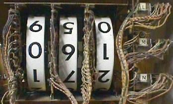
Most EMs from about 1960 to
1978 have mechanical score reels that spin, with the score printed on the reels
(earlier 1947 to about 1960 games usually have no score reels,
but have "lighted backbox" scoring with
the point value lit on the backglass; the exception to this is 1950s
multi-player pinballs, some Williams single player pinballs during 1953,
and some arcade games which had score reels starting around 1954).
This document applies to all types of EM
games (pinballs, pitch and bat baseballs, bowlers, gun games, etc.)
Electronic or Solid State games made EM games obsolete, and were released
starting about 1977. These games have electronic digital displays that show no score
when the game is powered off. Solid State games are not covered in this document.
Throughout this document there is a lot of reference to Gottlieb, and Bally, Williams, Genco, and Chicago Coin less. There is a reason I do this; Gottlieb EM pinball games are considered the "most collectible". But I do cover Williams, Bally, Chicago Coin and Genco too. All these games work essentially the same, though the exact mechanisms may be slightly different.
How About Gun Games, Bowlers, Pitch & Bat, and other EM Arcade Games?
This document can help with *any* type of EM coin operated device.
Though the emphasis is on 1947 and later flipper pinballs, all this information
applies to bowlers, pitch and bat baseballs, and other EM arcade games up
to about 1978.
EM games are 25+ years old. This means they have seen a lot of use. Many times these game have been purchases "as is" from a basement or warehouse or barn, and they haven't been serviced in many many years. And before getting to these storage places, often the games were played to mechanical death. Fixing them usually isn't just a simple, "fix what's broken", approach. Instead I preach a more systematic approach. The end result should be a good working game that will play for years and year (I find EM games repaired in this method to be extremely reliable, much more reliable than solidstate games). This method also works well because every game is wired different. There is no common circuit board used between games (like on solidstate machines). So understanding the schematics on each game can be overwhelming, especially for someone new to EM repair. This systematic approach should limits the amount of schematic reading needed (but you should definately get the game's schematics if you don't have them).
Probably the single biggest problem with EM games is the grease the manufacturers originally used to lubricate the "stepper" units in the game. With time this grease turns to cement, and prevents the steppers from advancing or reseting. This single problem prevents most EM games from working (or working correctly).
Got Schematics?
Having a schematic for a game would be ideal (but often the game can be fix
without it). If there is no game schematic, order one from someone on the
parts and repair sources web page.
For newer 1970s EM games a operation manual is also sometimes available.
It has reset info, game specific parts info, etc. Older pre-1970s EM games
only have schematics available in most cases (but there are some exceptions).
Is there a Repair Manual for my Game?
The short answer is "no", for most EM games there are only schematics
available (though starting in the 1970s many makers did offer a
booklet with each game explaining some of the relays and circuits).
"But I can't read the schematics, how am I supposed to
fix my game?" Again if you
follow the systematic approach outlined below and use your power
of observation, must often you don't need the schematics to fix
an EM game.
Voltages Inside EM Games.
Most EM games work at 24 to 50 volts for the coils.
One exception was Bally during the 1970s (50 volts), and Williams.
Williams used 50 volts AC for coil voltage until 1962 (Friendship7), when Williams
changed to 24 volts AC. The reason? Fifty volts is potentially lethal,
so Williams felt it was better to use a lower voltage.
But some games
(mostly Gottlieb) also use some 120 volt coils! Gottlieb's big reset
coils used for reseting banks of relays and some other start relays
use 120 volts. There is even 120 volts coming up to the coin door on
pre-1968 Gottlieb games (Sing Along/Melody and before).
Just be aware of this, and be careful!
1b. Getting Started: Necessary Tools
-
Fixing EM games will require a few tools. Luckily, most
are not that specialized and are easy to get.
- Work Light: I like florescent style work lights, as they don't break as easily if dropped.
- Screwdrivers: phillips and flat head, small and medium sizes.
- Large flathead screwdriver ("persuation" tool for locked coin doors)
- Electric screwdriver with 1/4" drive
- Magnetic extendable tool (Home Depot)
- Small mirror tool (Home Depot)
- Small flashlight (MagLite)
- Allen wrenches, assorted sizes.
- "T" handle allen wrenches.
- Nut Drivers: 1/4", 5/16", 11/32"
- Magnetic 1/4" nut driver
- Wrenches: 3/8", 9/16", 5/8" required, other sizes suggested
- Needle Nose Pliers
- Hemostat
- Right ratchet Angled Screwdriver with 1/4" bits (both phillips and flathead).
- Drill and Drill Bits
- Small wire brushes (Home Depot welding dept.)
- flat bastard file (for EOS and flipper cabinet switches, amoung other things).
- Wire cutters
- Dremel motor tool with a cutoff wheel
- Sharpie pen
- 6" adjustable wrench
- 4" adjustable wrench
- 6" channel lock pliers
- Super glue
- Heat shrink tubing (assorted sizes)
- Electrical tape
- Nylon ties
- Toothpicks
- Yellow or white glue
- Small hammer (I like a finish nail hammer)
- Small Chisel
- Small punch
- Razor blades
- Small sockets 1/4" drive (1/4", 5/16", etc)
- A white towel (that your girlfriend/wife will not miss!)
- Flex-Stone contact file (get several). Any good EM pinball vendor will have them. Alternatively, 400 grit sandpaper works well, folded into strips.
- Small Metal contact file.
- 240/400/600 Grit Wet/Dry Sandpaper or 3M Scotchbrite green pads. For cleaning stepper units, 400 Grit also works well, but I use what I have. If you're buying some sandpaper, get 400. Don't go less than 240 grit though, as it doesn't smooth things enough. Do not use steel wool (it creates a fire hazzard). The 3m green pads work really well, and last a long time.
- Contact Adjuster. Again available from a good EM pinball vendor. Personally I don't use one, but most people find them helpful when adjusting contacts.
- Light socket cleaning stick.
- Rubber light bulb remover. Handy for removing bulbs you just can't reach with your fingers.
- Palnut removal tool. Holds a playfield post in place while you remove the PAL nut or nylon locknut on top.
- Soldering Iron. A decent Weller SP23 soldering iron (25 watts) can be had at Home Depot or Lowes for about $15. Heck Big Lots often has a 25 watt soldering iron for $4 that works great for EM games. For more exacting electronic pinball work, MCM (800-543-4330) has Tenma #21-147 adjustable temperature soldering stations ($80, but often $40 on sale) that are great for both EM and solid state work.
- Rosin Core 60/40 Solder. This can only be bought at an electronic store like Radio Shack (hardware stores only sell 95/5 lead free solder, which won't work for EM games). Radio Shack's solder is made by Kester, and is good quality. I prefer the thinning size available (.037"), but that's me.
- Multi-Meter. If buying one, get a digital multimeter (DMM) with an audible continuity feature. Radio Shack sells one, but I would recommend MCM Electronics (800-543-4330). The Tenma #72-4025 is the best value for your dollar ($65, but often $40 on sale). You will need one that "buzzes" for continuity, and one that does low-ohm reading well. Again the Tenma 72-4025 is what I use. If working on electronic pinballs, this DMM works great for them too. Well worth the money in my opinion.
- Alligator clips with wires. Available at Radio Shack. These are useful for quickly jumpering contacts and lamps. Get the longest length they sell (usually 12 or 18 inches).
Non-Specialized Tools Required:
The white towel is useful when the playfield is tilted up, and working on the bottom of the playfield. Lay the white towel over the bottom panel of the game. If any parts fall when working on the playfield, they will be caught by the towel! (instead of rolling under the bottom panel, proceeded by searching and swearing). Don't forget to remove the towel before turning on the game!
These non-specialized tools are stuff you probably already have, or can buy at Sears, etc.
Specialized Tools Required:
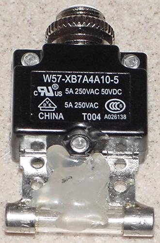
Circuit breaker.
When diagnosing an EM that always blows a fuse,
using a circuit breaker instead of a fuse is mandatory! (Unless you
like spending extra money on fuses.) I make a breaker easy-to-use by soldering a blown
fuse to a small PC board circuit breaker. Breakers are available from lots of places like
Mouser part# 655-W57-XB7A4A10-5 (Tyco 5amp breaker) and
655-W57-XB7A4A10-10 (Tyco 10amp breaker). I like the Tyco W57-XB7A4A10-5 as it's a
good quality and size, with a low $2 price. The Tyco breakers don't come smaller
than 5 amp, so if you want some smaller breakers for solidstate pinball work
(recommended!) check out
SMCelectronics.com.
After getting the proper breaker, just solder a blown glass fuse to the breaker's terminals (and use some silicon to help hold the fuse in place and to prevent the glass tube from breaking).
For EM work a circuit breaker the 5 amp size is perfect (I use 5 amp circuit breakers for the main EM solenoid and light fuses, and they work great). Anything below 3 amps will be too low for the solenoid circuit on a typical EM game for more than a couple seconds (mostly because the score motor consumes the most power, as coils are only "on" for just a moment). Remember circuit breakers don't blow as fast as a fuse, so you want to use a breaker that is lower amperage than the fuse it is replacing, which in most EM games will be 10 amps. It takes *forever* for a 10amp circuit breaker to blow in a game, so don't use a 10 amp circuit breaker for tech work (though the 10 amp does work well after you have the game all done, and you're out of fuses!) Better to use a cbreaker that is too low in amperage, than too high, when trying to diagnose a problem.
|
Here's a circuit breaker I modified with a blown fuse soldered to its lugs. Why the blown fuse? Because it makes installing the circuit breaker into a fuse holder a breeze! |
|
-
Cleaning & Lube "Tools" Required:
- Lubrication: Teflon Super Lube Gel (comes in a tube, looks like Vasoline), or CoinOp Lube (available from Williams dealers, basically 3-in-1 oil). I only use the Teflon Gel lube though as the others are antiques for EM fixing. Also using 3-in-1 oil is a rather temporary solution, as the oil dries out and must be re-aplied now and then, and can become gummy. Do NOT use White Lithium Grease as it dried out within a year and creates a huge mess. The Teflon Super Lube Gel does not dry out. Because of this I have highly recommend the Teflon Super Lube Gel. Radio Shack used to sell Telflon Gel Lube, but no longer called it Teflon lube (part number 64-2326, though it is still the same thing, but they are just calling it "Lube Gel"). Apparently Radio Shack just relabeled it for their stores, but now even the RS branded Lube Gel has been discontinued. Available from PinRestore.com. Or get it at precisionreloading.com/superlube.htm (get the 3 oz gel tube part# SP21030). I heard it is also at Lowe's as "Super Lube Synthetic Grease" (barcode 082353210305), but again it's not on their website. Also rumored Harbor Freight stores sell it, but again it does not appear in their website.
- Rubbing Alcohol (for cleaning stepper units and coil plungers, and cleaning rubber).
- Lighter Fluid or Naptha (good for cleaning dirt from playfield rubber, and cleaning really nasty stepper units).
- Spray Brake Parts Cleaner. Available in a spray can at automotive store. If you have a stepper unit that is frozen solid with old grease, this stuff will "unlock" the grease very quickly.
- Mean Green (available at local Dollar stores and Meijers). A good general cleaner and degreaser. Takes the yellow tobacco stains off cabinet paint.
- Novus #2 or MillWax (for cleaning pinball playfields and rubber). Stay away from the Wildcat products; their water-thin, solvent-based formula is not good for older playfields. Novus is available at many places (my local grocery store sells it), or from any good pinball vendor. I don't recommend MillWax (does it SMELL), but others like it (mostly because they have been around for a LONG time and are used to them). Personally I think Millwax is crap, with Novus2 being the best cleaner.
- Novus #3 (for polishing metal parts)
- Mr. Clean Magic Eraser (grocery store item), aka Melamine Foam. Use this with Alcohol, can often remove playfield dirt that no other cleaner will touch.
- Johnson's Paste Wax or Trewax Carnauba Wax (for waxing playfields). Johnson's paste wax or Trewax can be bought at a local hardware store or Kmart. Or any good Carnauba wax.
1c. Getting Started: Parts to Have On-Hand
-
When fixing EM games, I would highly recommend having some parts
on-hand to make things more convenient. All these parts are
available from someone on the
parts and repair sources web page.
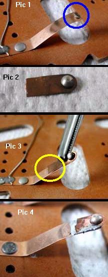
- New Switch Contacts: available in two sizes (the smaller one is for solidstate games and is gold flashed). The CU-CONTACT are tungstein face, copper backed for high current applications, and this is the one you want for EM games. I solder new contacts into existing blades a lot, especially on flipper and EOS switches, where they are worn or missing. Also needed for new switch blades.
- New Switch Blades: There come in one cutable length and several thicknesses. There is light thickness (.008), medium thickness (.012), and heavy thickness (.016). The heavy and medium thickness will be used the most, as those are the ones that break the most. The heavy guage are used for flipper and EOS switches, which break a lot. The medium gauge is used for most other applications (relays, playfield rollovers, etc). The light guage rarely breaks and is used for very low-tension applications (which rarely break switch blades). You can ask for an assortment, part# BLADE-LIGHT BLADE-MED, BLADE-HVY.
- Fish Paper: the insulating paper that goes between some switch contacts. You should have a few pieces around.
- Pop bumper spoons. The plastic type wears out, so it's nice to have some replacements handy #545-5610-01.
- Piano wire #MAT-MUSIC-KIT a nice assortment kit of piano wire. Handy for fixing all kinds of stuff, especially ball gates.
- Nylon Switch Lifters: These fall out of switch stacks and are impossible to find. There are several lengths available. I ask for an assortment. You don't need these often, but when you do...
- Lane guides. Yes there are a zillion different types. But nearly every game has at least one broken lane guide.
- Coil Stops: Bally A613-67+ for most Bally EMs.
- Coil Stops: Bally A613-127+ for linear Bally flippers.
- Coil Stops: Williams A8143+ AC or DC coil stop for most Williams EM and early solidstate games.
- Coil Stops: Gottlieb with replacable core.
- Slingshot Plunger & link: I keep Williams ones around as they seem like they break the most.
- Pop bumper metal yoke 1A-5492, used on gottlieb and williams and bally.
- Pop bumper fiber yoke 1A-5493, used on gottlieb and williams and bally.
- #47 light bulbs: have 50 or so around. One hundred is plenty to do most games. Do not use #44 bulbs, as they run hotter and consume more energy. Fortyfours are especially a problem when used behind backglasses (the extra heat can help delaminate the paint from the glass).
- Lamp sockets: these are a constant source of problems in EM games. Each game is different, but I keep a good supply of backglass lamp sockets (as short as possible). Playfield sockets can often be repaired, and there are so many different styles it is hard to say which ones to stock. I always have a good supply of pop bumper lamp sockets around.
- Fuses: at minimum 10 and 15 amp fast blow fuses are needed, and 1 and 5 amp slow blow fuses. I would have five of any value on hand at all times. Get 250 volt versions, and avoid 32 volt fuses. Radio Shack sells fuses for a decent price.
- Fuse Holders: fuse holders often break (especially for Bally EM's), leaving a game non-operational #FUS-HLDR.
- Nylon Coil Sleeves: the 1.75" or 2" variety is most often needed when rebuilding flippers and other EM coils (manufacturer specific). Also get some 'double flanged' coil sleeves, used in knocker, bell and chime coils.
- Chime plungers. This is a metal coil plunger with a nylon tip. Williams/Gottlieb and Bally use two different sizes, have both on hand.
- Coil stops. Bolt-on coil stops can often be purchases, especially for Gottlieb games. I keep a couple around.
- Coil plunger with a nylon tip for bell, chime and knocker coils (the nylon tip is often broken on these plungers, causing metal to metal contact, and ultimately breaking the bell, chime or knocker).
- Hair pin clips. You can get assorted sizes of these at Home Depot.
- "C" and "E" clips. Again Home Depot, get their smallest size and up to 1/4".
- Line cord. Go to the Dollar Store and buy some cheap 15 foot extension cords, cut off the female end.
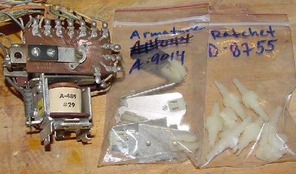
- Relay springs. Often these are broken or get lost. For Gottlieb, the spring an old-style magnet type relay is part# A-4965. For the newr plastic armature plate Gottlieb AG relays part# A-5081. Old style interlock relays used spring part# A-4965 for the coil with the armature plate that the switch stack rests, and A-574 for the other relay. New style interlock relays used sprint part# A-5081 on the relay that has the plastic armature plate, and sprint part# A-574 for the other relay.
- Flipper Rebuild Kits. Instead of getting the separate parts, you can often get complete rebuild kits.
- Aluminum bar 1.5" wide 1/8" thick. Home Depot sells three foot lengths of aluminum bars. Buy one and keep it around, as it works great for 1970s EM Chime units. Just cut the bar to the proper length, drill two holes, and you have a new chime bar (these are often missing, broken, or have holes blow through them from using a metal plunger with a missing nylon tip). The short bars are usually the most damaged (because they are the 10 or 100 point chime). William chime bar lengths: 5 3/4", 6 7/8", 7 3/8" with two 3/8" holes 3 1/2" center to center. Bally chime lengths vary, but are usually 4 7/8", 5 3/8", 6", 6 7/8" with two 1/2" holes 3 1/8" center to center.
- Plumbing rubber washers 1/4" ID. I used these underneath the chime bars so they don't sound so 'metallic'. You can also use rubber grommets or felt grommets, but these are much more expensive then flat plumbing washers.
- Fiber Flipper Links and Plungers: used when rebuilding flippers (game specific).
- Bridge Rectifier 2502 or 3502 (35 amp 200 volt), aka VARO (this is what the schematics often call a Bridge). 1970s Bally and Williams EMs use a bridge rectifier for the pop bumpers, which run on DC voltage instead of AC. The bridge can short (blowing a fuse) or go open. Get a lug style 25 amp 50 volt (or higher) bridge rectifier (available at Radio Shack).
- Flipper Rebuild kit. Flipper rebuild kits for most EM games. I highly suggest these as they include all the parts to completely rebuild a flipper making is strong and like-new.
- Pop bumper caps. These are often broken or incorrect.
- Shooter Barrel Spring: the short chrome spring on the outside of the shooter mechanism on pinball games. These rust and look like crap in short order.
- Balls: a new pinball will make your pinball playfield last longer. Pinballs use 1 1/16" balls. Pitch and bats usually use either 7/8" (pre-1960) or 3/4" (1960 and later) balls (game specific).
- Leg Levelers: replace those old crummy looking leg levelers with brand new ones. 3" are used on newer solid state games, and 2" levelers are used on EM's. Avoid import leg levelers if possible; the feet rip off very easily.
- Rubber Rings: It is a good idea to order game-specific ring kits with exactly the rings needed (though I have an assortment of all sizes always on hand). Get white rings, as black rings are harder and have less bounce, and produce more black dust. Also black rings look dumb on EM games, and are designed for 1995 and newer electronic pinballs. For pinballs don't forget to get flipper rubber, a shooter tip, and a rebound rubber (the round brown rubber donut at the top of the playfield).
- Lock: a new lock for the coin door and maybe the back door is often needed (don't forget to look inside the coin door; sometimes the back door key is hanging there).
- 75 ohm, 100 ohm, 125 ohm, 150 ohm 10 watt resistors (for 1950s, 1960s and 1970s Gottlieb EMs). Some feature lights on these games use solenoid voltage (28 volts) as the power for these 6.3 volt #47/44 bulbs. Gottlieb uses a large sand resistor to knock the 28 volt current down to 6 volt levels for these feature lights. Often the reisistors are broken or out of spec. Also in the 'old' days, line voltage was 110 to 115 volts. Now it's more like 120 to 125 volts. Because the solenoid voltage is not regulated, this means the 75 ohm resistor (even if good) is not enough ohms, and the feature light bulbs burn too bright (cooking the bulbs and any plastics or backglass art around them). In addition, if you have the game on high tap, the 75 ohm resistors are definately not enough. I usually end up at 125 or 150 ohms for proper lamp brightness.
Parts to have:
|
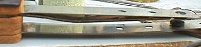
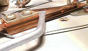
The bottom panel of a 1976 Williams Space Mission. Note all the metal filings! These come from the metal coil sleeves installed in this game from the factory, which wear as their metal plunger strokes inside the metal sleeve. Metal coil sleeves should be replaced on all commonly used coils (flipper, slingshots, chime bells, pop bumpers, etc.) with new *nylon* coil sleeves. If the original metal coil sleeve won't come out of the coil, the whole coil needs to be replaced (nearly all new coils use nylon coil sleeves, with the exception of some really large coils like Baseball bat coils which could have an aluminum or brass coil sleeve). New nylon coil sleeves will also "dry lubricate" the coil plunger, and make the coil have more "snap" and better playing action. |
|
|
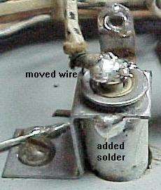
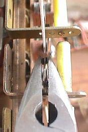
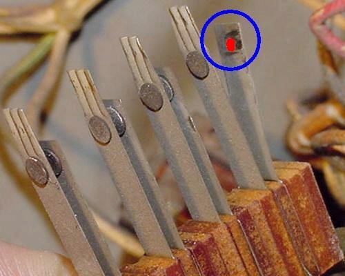
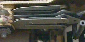
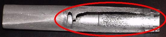
Here's a picture of a worn out aluminum coil sleeve! Note the red circle showing where the coil plunger wore right through the sleeve. I have never seen this happen to a nylon coil sleeve. This sleeve came out of a 1 point bell coil. This was replaced with a new nylon "double flanged" coil sleeve. |
|
|
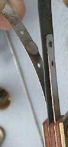
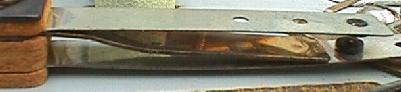
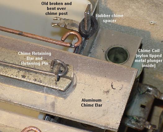
Another high-wear part on 1970s Williams EM games (Space Mission). This is the chime "box", which uses three aluminum bars of different lengths for different chime tones. There is a coils for each bar with a nylon tipped metal plunger that hits the bar. With time, the hole in the aluminum bar retaining post that the retaining pin goes through will enlongate and eventually break (as seen in the bent over post below). If the nylon tip breaks off the metal coil plunger (common), this problem will happen even faster. Also note the groove worn in the used retaining pin. A new chime box and retaining pins will need to be installed, or the old posts and pins replaced with new metal posts and pop riveted in place (as seen here). Also note the rubber spacer for the chime has been replaced. If this is not done, the chime will sound frail and harsh. An old rubbon playfield post sleeve (as used on 1990s pinball games) was cut to replace the old rubber spacers (two used on each post, one under and on top of the chime bar). |
|
1d. Getting Started: Lubrication & Why Contact Cleaner/WD-40 are BAD.
Lubrication in EM Games.
Electro-Mechanical machines, for the most part, do not use
any lubrication. Most parts run "dry". Far more damage can be done to a
machine by over-lubricating, than by under-lubricating.
As a rule, if in doubt as to lubrication,
don't do it! Throw that WD-40 away, it won't be needed here (besides,
WD-40 is very flamable, and with EM switch arcs, it could start the game
on fire!)
As a general rule, keep this in mind for EM moving parts: Metal to metal lube is OK. Nylon to metal NO lube. Nylon to nylon NO lube. And NEVER EVER lubricate the moving metal plungers inside coils (even if the metal plunger is moving inside a metal coil sleeve). Also NEVER lubricate the gears of the score motor.
In regards to nylon, all reference I can find from professional plastics companies speak of Nylon: "no lubrication required". In fact a number of them mention how Nylon can be worn by various greases that collect dust and act as an abrasive paste! There is also a concern about Nylon expanding when it it lubricated. This is just more evidence that you should not lubricate any nylon parts.
Generally the only parts that will require any lubrication are stepper moving "fingers" and some other metal-to-metal moving parts. There aren't very many in an EM game. So keep that lubrication in the tool box and away from the game. I tend to only use lubrication on stepper units and not much more than that. I used them on some 1950s score reels too (metal to metal) such as the pivot points for rotating arms.
When there is a need to lube an EM game, using the right lubricant is very important. Do not use white grease. Do not use WD-40. White grease solidifies and WD-40 gums up in a short amount of time. Do not use silicone-based lubricants either.
The only lubricant needed is Teflon based lube (that Radio Shack used to sell), or simple #10 oil, or Williams CoinOp Lube. Personally I like the Teflon Lube Gel. It's available from precisionreloading.com/superlube.htm and pinrestore.com as "Super Lube". Get the 3oz gel tube. This stuff is the best EM lubricant and the only EM lubricant you will need.
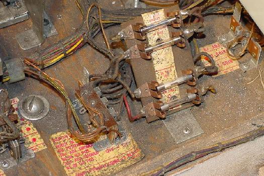
Contact Cleaner & WD-40 are BAD for EM Games.
WARNING: DO NOT USE CONTACT CLEANER OR WD-40 IN EM GAMES!
Sometimes first-timers will use contact cleaner
on the switch contacts of an EM game (somehow they
think a chemical will solve a mechanical problem!)
DO NOT SPRAY EM GAMES *ANYWHERE* WITH CONTACT CLEANER!
Spraying switch contacts with contact cleaner or WD-40 does some
really bad things, AND IS EXTREMELY DANGEROUS in EM games.
It is also guarenteed to make the game
fail and not work as time progresses.
Contact cleaner is made for LOW VOLTAGE situations. Low voltage means +5 volts. EM games are HIGH VOLTAGE. Contact cleaner is *not* designed for high voltage, and does *nothing* to fix or clean a high voltage switch! Really contact cleaner was made for gold or tin low voltage (+5 volts) switch contacts, not the silver or tungsten high voltage contacts used in EM games. Don't try and use a chemical to solve a mechanical problem.
Also contact cleaner and WD-40 is *extremely* flammable. I have seen people spray it in a game, turn the game on, and the game burst into flames! Because of the high voltage and the switch arc, the contact cleaner explodes into a ball of fire. Typically this will start the cotton cloth wire insulators on fire too, rendering the game unrepairable (after the fire is put out!) All that is left is bare wire with no insulation.
|
Contact cleaner lights up BIG with only a spark! |

|
|
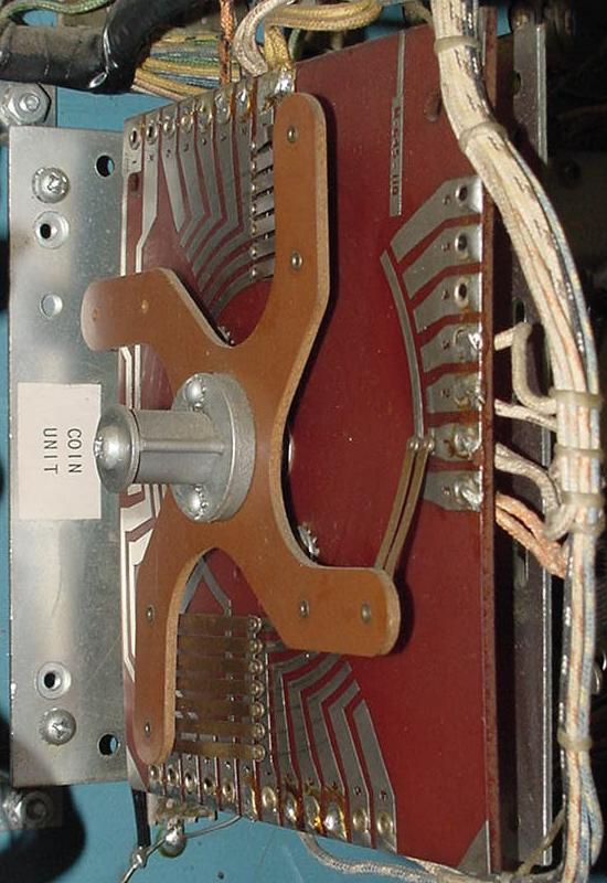
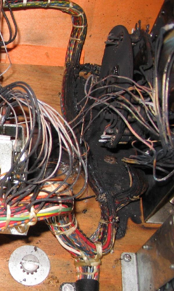
The Coin unit on the bottom panel of an EM Gottlieb that was sprayed with contact cleaner. The game started fire, burning all the wiring and the Coin unit itself! This is just ONE reason why you don't want to use contact cleaner. If this is going to be fixed, ALL the burnt cloth-covered wire in this area will need to be replaced. Also the bakelit plates on the Coin unit will also probably need to be replaced too, because they will be very brittle. |
|
-
Also, contact cleaner in the presence of an electrical arch
(which is seen on all high voltage EM switch contacts),
causes a chemical reaction. This reaction produces
phosgene gas (COCl2
which is mustard gas!) and free chlorine. The free chlorine attacks
the silver EM switch contacts and makes silver chloride (an
insulator). The game now has this white, insulating material
on the switch contacts! Once this happens, the switches will
not work. It's like putting a piece of tape between the
switch contacts.
Silver chloride (an insulator) is completely different than silver sulfide, which is a conductor. Silver sulfide is the black dust normally seen on switch contacts (the black dust is not necessarily a bad thing).
There is no reason to use a chemical for a mechanical problem. Dirty and mis-adjusted switches is a mechanical issue. And you don't solve this type of problem with a chemical.
The other problem with contact cleaner is most people spray WAY too much of it. This allows contact cleaner to get into the bakelite switch spacers, the wire insulation, and the plywood around the switches (the bakelite switch spacers can shrink with contact cleaner, changing the gapping of the switches). This over-use of contact cleaner provides a constant source of the cleaner, and causes even more problems down the road. And after the user thinks it's all clear to turn the game on, BOMB it bursts into flame (again!)
If you insist of having to "clean" out your game, the best I can offer you is to do it this way: Take the entire bottom panel out of the game, and bring it outside. Stand it on end and use some compressed air to blow off the dirt and crud. That's as far as you should go when "spraying" the switch contacts on a game.
1e. Getting Started: Electrical Parts of an EM Game.
Before trying to fix an EM game, it's a good idea to know something about the parts inside the game that we will be working with. With a general understanding of the following, fixing an EM game will be much easier. EM games consist of several electrical and mechanical parts. Each of these is described below.
-
A transformer is two (or more) coils of wire wrapped around a ferrous core.
The 'primary' coil (wall voltage) creates a magnetic field, which is coupled
into (usually two) secondary coils. This produces lower voltages
to power the game's lamps and solenoids. That is,
the game's transformer takes AC wall voltage and steps it down to
the appropriate voltages needed for the game. This usually
includes 6 volts AC for the lamps, and 24 to 30 volts AC for the
solenoids. One exception was Bally during the 1970s (50 volts), and Williams.
Williams used 50 volts AC for coil voltage until 1962 (Friendship7), when Williams
changed to 24 volts AC. The reason? Fifty volts is potentially lethal,
so Williams felt it was better to use a lower voltage.
Some manufacturers (Williams in 1972,
and Bally in 1975, and Gottlieb in 1978) then convert the AC voltage to DC using
a bridge rectifier for some coils. Genco also used DC voltage in the 1950s,
by using big selenium rectifier disc plates mounted on the transformer
to output about 18 volts DC for the solenoids.
Does a transformer ever go bad? Short version - NO. But I hear this all the time from inexperienced EM (and solidstate!) repair people - "the transformer is bad". In fact, this is never the case. In all the EM games I have fixed (I fix about 200-300 per year), *never* has the transformer been bad. I have seen one bad transformer though, and it was so obvious it was bad (it was a melted bloob of goo, since transformers are potted in wax, as they heat up and the winding burn, the wax melts and burns too).
Luckily EM transformers are very easy to test. The primary wall voltage comes in on two lugs, and the transformer outputs at least 6 volts (for the lights) and 25 to 50 volts for the solenoids). So there are usually three output lugs, with one 'common'. Put a DMM meter on AC voltages and one lead on 'common'. Put the other lead on one of the other lugs and check for 6 volts AC and 25 to 50 volts AC. Note 'ground' is not a reference point here, the common lug is used instead.
Genco's DC Dilemia.
Unlike everyone else, Genco used DC voltage to power all their coils at about 18 volts.
To do this, they use a selenium rectifier to convert the transformer's AC
voltage to DC volts. This style of rectifier was
used before the invention of silicon diodes. Selenium rectifiers are notorious for
failing gradually over time, and then dying suddenly.
It is not a matter of "if" a selenium rectifier will fail, but rather
"when" it will fail.
Selenium rectifiers fail because they develop high,
internal series resistance, resulting in lower bias or "C-supply" voltage.
Their forward voltage drop increases to the point
that they no longer convert AC voltage to DC.
As this happens, the increased resistance causes the rectifier to heat up,
which eventually causes it to burn. When this happens, it emits a
highly pungent and nasty odor, and could start a fire
(selenium rectifiers probably reached their peak
in TV sets of the 1950's).
Nowadays their use would probably be restricted
in consumer products because of the toxicity of selenium.
The biggest symtom of a failing Genco selenium rectifier are coils that are "weak". For example, the classic case is the bell solenoid just doesn't have enough juice to ring the bell. The bell plunger goes up, but it doesn't strike the bell with enough force to actually sound the bell. Or when the score reels or continuous units reset, they do it lathargetically.
Because of this, the selenium rectifier should be replaced with a conventional bridge rectifier. Radio Shack sells a 25 amp 50 volt bridge with lugs that works just fine, though I personally use a 35 amp 200 volt bridge (because I already have them around for solid state games and their power supplies).
The new silicon bridge is easy to hook up to the Genco transformer. Just remove the two top outside green wires going from the transformer to the selenium rectifier, and connect them on the two AC lugs of the bridge (the bridge's AC lugs are diagonal to each other, and usually at least one is marked "AC"). One of these transformer leads should go through a 10 amp fuse (which would blow if the new silicon bridge shorts, which does happen).
Then the upper solo output wire from the selenium rectifier (which has a cloth wire going to the harness) should then be connected to the negative lug on the silicon bridge. The "+" (positive) silicon bridge lug is then connected to the transformer's top center lead, which also connectes to the old selenium rectifier (cut the connection to the old rectifier though). After mounting the wires, put a wood screw through the hole in the center of the silicon bridge, and screw it to the wood panel. Leave the original (and now disconnected) selenium rectifier there, for that "original" look.
|
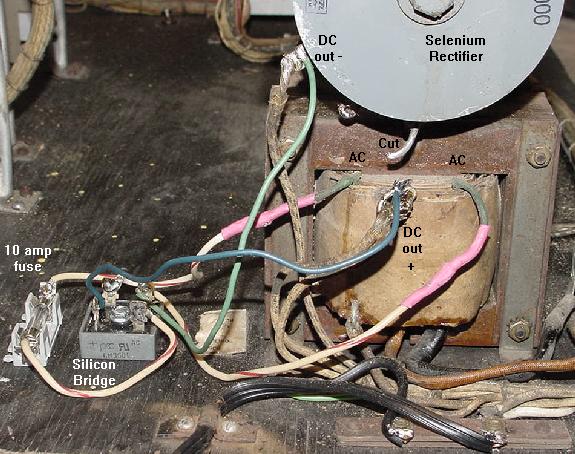
A 1954 Genco 2 Player Basketball which has been converted from using the original Selenium rectifier, to a new silicon bridge rectifier. Note the 10 amp fuse installed too, on one AC lead going to the silicon bridge. |
|
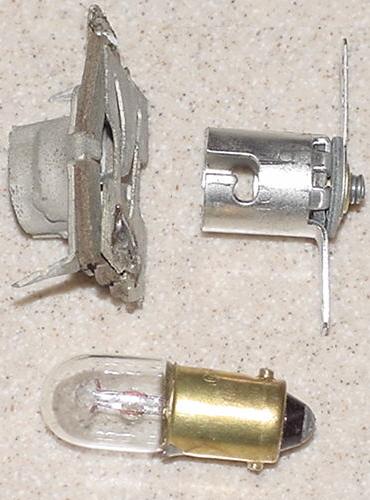
Lamps.
-
All games use lamps. The most commonly used lamps are 6 volt AC with bayonet bases
(#44, #47 or #55). Many arcade games use 120 volt florescent lamps too.
But other lamps are sometimes also used, especially on Genco games
(#1458 lamps, 20 volts). Number 67 lamps are also used
on some arcade games, which are a larger 6 volt version of a #44. And
flashing lamps (#455) are often seen
behind pinball backglasses. These 6 volt lamps have a
thermal switch that when it heats up after a
second, the metal expands and opens a contact, turning the lamp off.
After cooling for a second, the metal contracts and closes the contact, and
the lamp lights again. This process repeats over and over.
Switches.
-
EM games use lots of leaf switches. These switches have two
or three contacts attached to metal blades (the "leaf"). Between
the switch blades are bakelite insulators. Switches come
basically three ways: Normally Open, Normally Closed, or Make/Break.
The schematics show if a switch is normally open or closed. Note the schematics
identify all the switches when the game is turned on, reset, and ready to play
with the first ball in the shooter lane. Other arcade games like pitch & bat and
bowlers are pretty much the same, with the game reset and ready to play the first ball.
This is important to know as it dictates how a switch will behave relative to
the schematics and whether it is "normally open" or "normally closed".
|
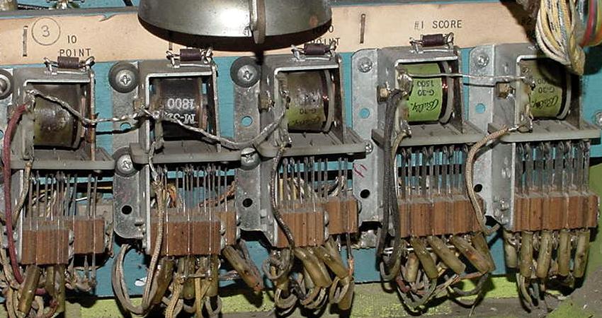
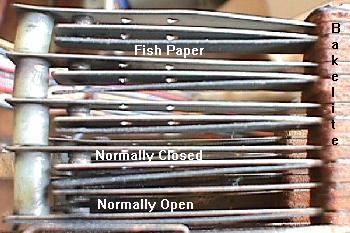
Note the four Normally Closed (top 4 pairs) and one Normally Open (bottom most pair) leaf switches in this switch stack. All are quite dirty with black dust. |
|
-
Normally Open means the two contacts are open, and not connected. Activating this
switch closes the two contacts, and turns on the circuit. Gottlieb identifies these types of
switches as "A" contacts.
Normally Closed means the two contacts are closed (touching), and are connected. Activating this switch opens the two contacts, and turns off the circuit. Gottlieb identifies these types of switches as "B" contacts.
Make/Break means there are three contacts on the switch. A middle or common contact, a normally open contact, and a normally closed contact. When this type of switch is activated, it closes the normally open contact, and opens the normall closed contact. Gottlieb identifies these types of switches as "C" contacts.
Bakelite Insulators are the small brown fiber-looking plates between the switch contacts. These insulate the switch blades from each other in the switch stack.
Fish Paper is an insulating gray paper used between switches, mostly in switch stacks. It prevents one set of switch contacts from shorting against another. Often this paper gets worn and damaged. This can cause adjacent switches to short. Inspect the paper, and replace where necessary.
-
A relay is a small coil that pulls in, and activates (or deactivates)
a number of switches. One switch
turns on the relay coil, which in turn activates a number of other
(normally open or normally closed) switches. This amounts to the action of one circuit
controling many more circuits, without an electrical connection to them!
A relay consists of a coil of wire wrapped on a ferrous core or 'bobbin'. A ferrous activator plate is held above the core of the coil. Activated by the plate are one or more pairs of switch contacts. As the relay energizes, it pulls the activator plate towards the wire coil, changing the state of switch conductivity (for example making a "normally open" switch close).
An example of this would be a feature relay that is activated by a pinball playfield switch. This can turn on a relay, which will then turns on (or turns off) many other switches, which can score points and turn on numerous playfield lights. Or a low voltage 30 volt relay could turn on power to a high voltage 120 volt coil.
|
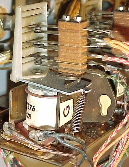
A Gottlieb pop bumper relay. The playfield switch turns this relay on, which in turn energizes the pop bumper and triggers the 10 point relay to score the points. This relay has three Normally-Open switches. |
|
-
AC voltage relays have a copper "slug" center surrounded by an iron center. AC
coils have a coil stop made with these same materials. This
material creates a small magnet. This holds the magnetic field of
the coil as the AC (alternating current) moves through zero volts
(remember, AC volatage alternates from a positive voltage, to zero
volts, to a negative voltage, and back to zero, then to positive
voltage, and so on). An AC relay or AC coil stop will work in a DC
circuit, but a DC relay or DC coil stop won't work in an
AC circuit.
|
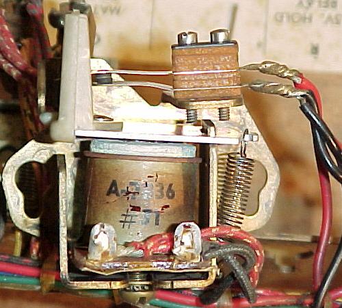
A Gottlieb Hold relay. This hold relay is the style used in games prior to 1968 (Sing Alone/Melody and before). Once the game is on and play is started, this relay is energized until the game is turned off. Hence the toasty brown paper wrapper from this relay's constant use. |
|
-
Relay coils usually have a resistance of 10 ohms or greater. The higher
the resistance, the less magnetic pull the relay will have, but also the less chance
the relay coil will heat up and burn if it is energized for a long time.
Because of this, some relays are designed so they may stay on
for long periods of time.
These hold relays usually have higher resistance coils, like
100 ohms or more, and are designed to stay on sometimes the entire time the game is
turned on. Hold relays are often used for the game power hold
and coin mechanism lock outs, or for toggling a set of features on a game.
Relays also come in different Frame sizes. The two relays shown above are "short frame" relays. Companies use these relays in situations where a smaller footprint is needed, and a fast reaction time (like pop bumper relays). "Long frame" relays are used where space isn't such an issue. Long frame relays are easier to adjust and visually diagnose, and hence tend to be more reliable in operation.
|
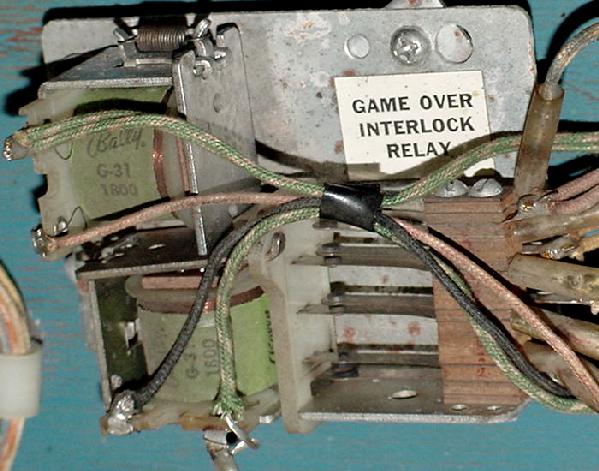
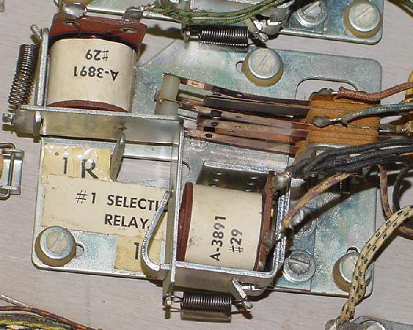
Latch-Trip Relays: a latch-trip relay is used as a hold relay. The Bally latch-trip relay is used for the "game over" switches. This particular game-over latch-trip relay is the source of many Bally problems. 1970s Gottlieb latch-trip relays are particularly nasty as the switch travel is small, so the switches must be very accurately adjusted. |
|
|
1960s Gottlieb "long frame" Latch Relay (Flipper Parade). |
|
-
A subset of the hold relay family is the Latch-Trip relay
or Interlock relay.
Basically it's two relay coils that control one set of switches.
The pull-in (latch) relay coil activates the switches, and a metal armature plate locks
the switches mechanically (even when the pull-in latch coil is not energized).
When the second release relay coil activates, it un-latches (trips) the lock
and releases the metal armature plate. A latch-trip relay can retain its state without being
constantly energized (unlike a hold relay). A latch-trip relay can even retain
its state if the game is turned off.
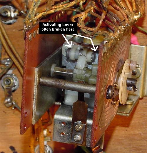
Latch-trip relays are a common source of problems. For example, if a Bally or Williams pinball won't light up after turning it on (and pressing the left flipper button!), often this can be traced to the switches in the game-over latch-trip relay. Gottlieb "short frame" latch-trip relays used during the 1970s are even more troublesome (Ax/Bx relays on multi-players, Ax on single players). The switches in Gottlieb short frame latch-trip relays have a very small amount of travel. This means they must be adjusted perfectly to function correctly. Also the Ax/Bx switches can come out of their actuator plate slot (usually because someone messed with it and unknowningly knocked the switch blades out, and if they are not put back in the correct slot, the switch gaps will be all wrong and the game will never work.)
|
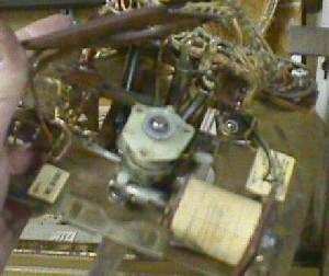
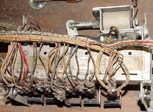
A Gottlieb relay bank (Flipper Parade). This relay bank houses a mere five relays. The reset solenoid can clearly be seen at the top. |
|
-
The last type of relay configuration is the relay bank. This
consists of a number of relays (generally four to twenty)
mounted on a common frame. Each relay can be
"tripped" individually, much like the trip relay in a latch-trip system.
When a relay coil is energized in the relay bank, it releases an armiture plate
which opens or closes the relay's associated switches. When the relay is
de-energized, the switches stay in their new tripped position. The beauty
behind the relay bank is the reset. With a single solenoid connected to a moving bar
on the relay bank, the bank can reset all of its relays to their untripped position.
Some early pre-1954 pinball games have a manual reset bar for the relay bank,
which the player unknowingly resets when they insert a coin into the front
door coin slide mechanism!
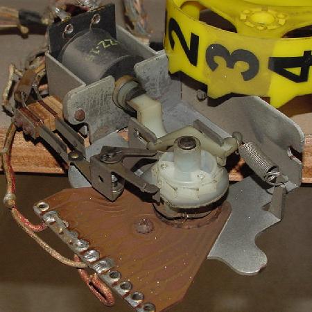
|
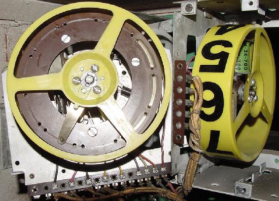
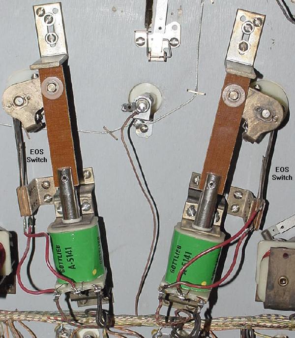
New Hi-Power Gottlieb Flipper coils ("yellow dot"), with new fiber flipper links attached to the plungers (Kings & Queens). New links will make your old flippers work like new, as does a new coil sleeve. The hi-power coils are about 10% stronger than the originals. Note the EOS (end of stroke) switches for each flipper. |
|
Solenoids (Coils).
-
Solenoids (coils) are bigger versions of relay coils.
A coil of wire wrapped around a plastic 'bobbin', but with a hollow
center core (unlike a relay which does not have a hollow core).
A ferrous plunger is pulled into the solenoid's core when power is
applied to the coil. Solenoids are a transducers, converting electrical
energy into mechanical energy. The mechanical energy can be used to move
a pinball in game play (slingshots, flippers, pop bumpers). Or solenoids
can advance or reset mechanical counting units ('steppers')
like a Ball-in-Play or Player mechanism.
Solenoids are much larger than relays, and usually have much lower resistance. Most coils have a resistance of 2 to 120 ohms (less than 2 ohms and the coil is becoming a direct short, and will blow a fuse!) The lower the resistance of the coil, the more powerful it is (for example, pop bumper coils tend to be about 3 ohms). High resistance coils are made to stay turned on. This includes the ball release coil (on pre-1967 Gottliebs), and the hold side of a flipper coil (more on that below). But for the most part, coils can only be on for very short periods of time (otherwise they will smoke and burn). Solenoids have a center hole through which a plunger travels until it hits a "coil stop". When a solenoid is switched on, it sucks this plunger down inside the solenoid coil.
Flipper Coils are a unique type of solenoid. This coil is actually two coils in one package. One part of the coil is the high-powered side, and is usually about 3 ohms. This uses large diameter wire, with a limited number of turns (low resistance). Since there is low resistance, the power can travel quickly and easily through these windings. This part of the coil gives the flipper its initial power to kick the ball.
The second part of the flipper coil is the hold side, and is usually about 100 to 150 ohms. This acts much like a hold relay; lots of turns of thin wire with high resistance. This part of the flipper coil is normally shorted out and bypassed by a normally closed end of stroke (EOS) switch.
It works like this: When the player presses the flipper button, the high-powered side of the flipper coil is activated, and the low-powered side of the coil is bypassed. The high-powered side of the coil moves the flipper plunger through it's stroke. As the flipper reaches it's end-of-stoke (EOS), the flipper pawl opens the normally closed EOS switch (which has shorted out the low-power side of the flipper coil). When this switch is opened at the end of the flipper's travel, the electricity passes through both the high powered and low-powered sides of the flipper coil in series (one after the other). The combination of these two coils together (with a combined resistance of the two coils) allows the player to hold in the flipper button without burning the flipper coil. If the high-powered side of the coil was activated alone for more than a few seconds by itself, the coil would get hot, smoke, smell, and burn, and probably blow the game's solenoid fuse.
Score Motor.
-
Almost all post-WW2 EM games have a score motor (except Genco EMs).
The score motor comprised a small electric AC motor (about 25 RPM) that is speed
reduced through some gears. Attached to the motor shaft are several
disks (also called cams) with indentations around the outside. Stacks of multiple
switches surround the cams, which have a lever. The switch levers
either rides around the outside of the rotating cams, or they
come in contact with pins that perturd perpendicturly to the cams.
As the cams turn, the switches open and close, as dictated by the
indentations or pins in the cam (via the switch levers).
Score motors also have a "Home" or "Motor Run" switch. The purpose of this switch is to keep the motor in motion (after some external circuit started the motor) until it finishes turning through a "cycle", ultimately resting at a "home" position. Most score motors have two to four cycles per cam revolution.
This is all fine and dandy, but what purpose does the score motor serve? Its job is to make a certain feature repeat a desired number of times. For example, say in a pinball machine the player hits a 50 point target. To score 50 points, the 10 point relay must be engaged five times. This repeated usage of the 10 point relay is done using a 50 point relay and the score motor. The 50 point relay engergizes, which turns the score motor on for just a moment. Once the score motor is on, it will continue to turn one cycle, and then shut off (thanks to the home switch). As the score motor turns through its one cycle, a score motor switch is opened and closed (pulsed) five times which turns on and off the 10 point relay, through a closed switch on the 50 point relay (which is still energized thanks to yet another score motor switch). This registers the required 50 points on the score reels. After the five pulses of the score motor switch and the completed cycle, the score motor stops and the 50 point relay de-energizes (because of yet another score motor switch opens turning the 50 point relay off). This whole process takes about one second, and involves a number of switches. It's computer logic without the computer!
Another usage of the score motor is for reseting the score reels to zero when a new game is started. Each score reel (discussed more in detail below) has a zero position switch that opens when a the score reel is at zero. Using a reset relay and a score motor switch, a circuit to the score motor is used that pulses the score reels until they all reset back to zero. Once all the score reels' zero position switches are open, the score motor circuit opens, and the motor stops turning. Again, as with the 50 point example above, the score motor is used to do a task (pulsing the score reels) multiple times.
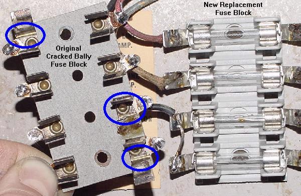
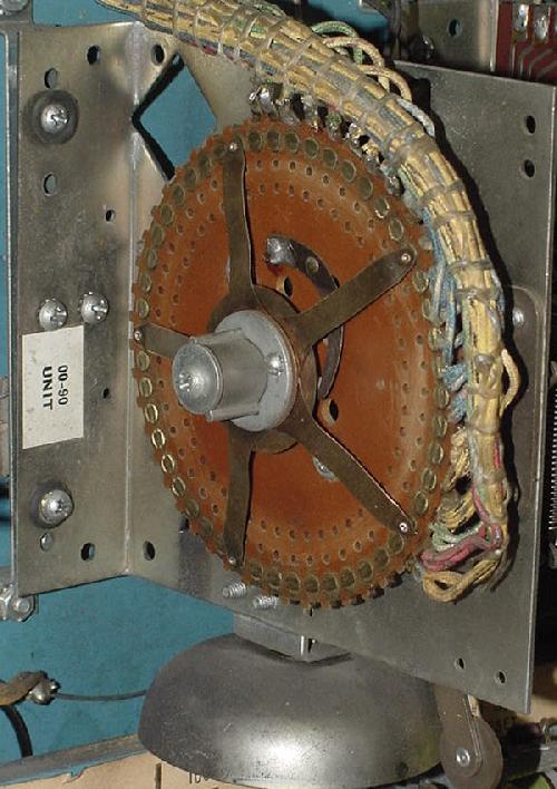
|
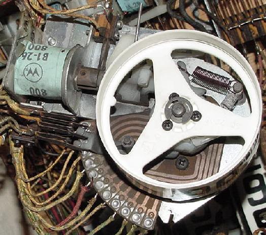
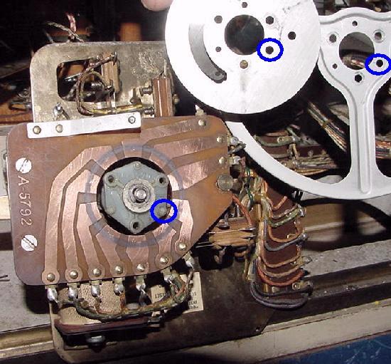
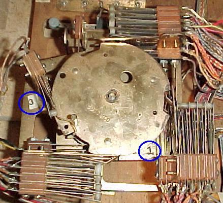
A Gottlieb score motor, top view. The blue circles indicate two of the switch stack numbers (from 1 to 4). |
|
-
Because the score motor has several different levels (cams), and many
switches associated with each cam, a numbering system was created
to identify the switch stacks. This number format is usually shown
on the game's schematics. On Gottlieb score motors,
numbers are used to identify the switch mounting brackets (usually from one
to four). Letters are used to identify the switch stack's level (cam),
with "A" being the level closest to the bottom board, and "E" closest to the
playfield. If the schematic referred to switch "4C", this meant the switch
was located in the switch stack mounted on bracket number four,
and was the "C" (middle) level. Note there could be as many as five or six
individual switches on the switch stack 4C! In order to find the exact switch
in question, the schematic also identifies the switch's wire colors (and hopefully
the game's wire colors have not faded!)
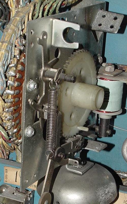
|
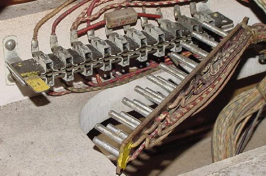
A Gottlieb score motor, side view. Here the "A" and "C" switch levels can be clearly seen ("A" is closest to the bottom of the picture). |
|
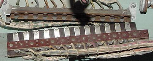
|
Bally score motor cam and switch stack scheme (Bally Gator). Again the "A" switch is closest to the bottom board. |
|
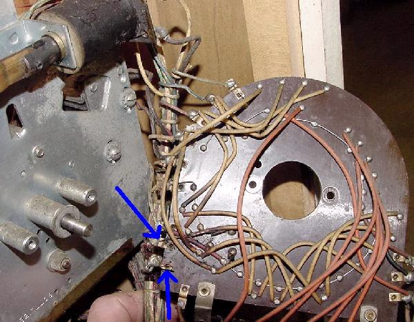
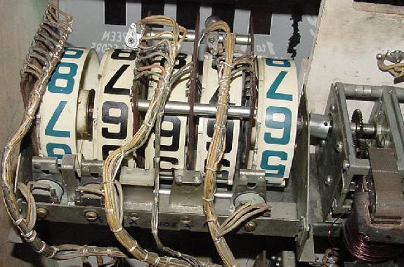
Stepper Units.
-
If relays are the most common device in an EM game, steppers
are the second most common (and largest).
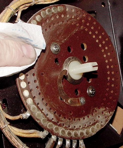
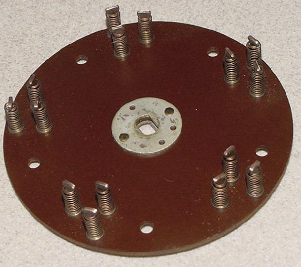
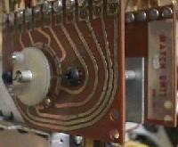
Most steppers consists of a metal frame with a brown insulting material
containing lots of small metal contacts, grouped in circles.
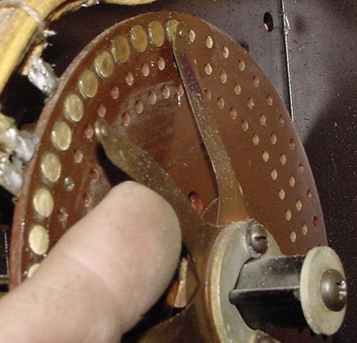
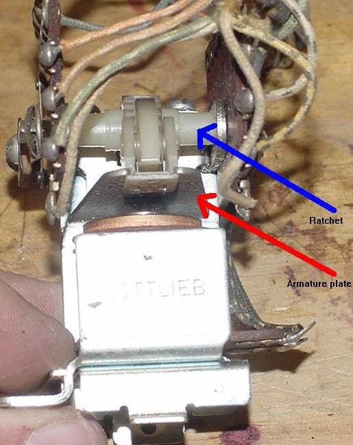
There is a ratchet mechanism to advance "contact fingers" or "wiper blades",
which touch the small metal contacts on the brown insulator
(as many as 50 wires can be soldered to the contacts on a single stepper unit).
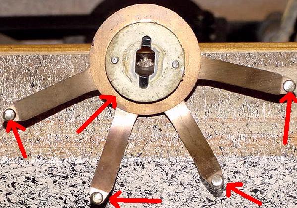
Wipers are a type of switch on the stepper unit that rotate with the unit.
As the stepper unit moves, the wiper blades make contact with a different
set of copper contacts. This is used to change features or scoring on a game.
In addition there is one or two solenoids that energize to move the
contact fingers.
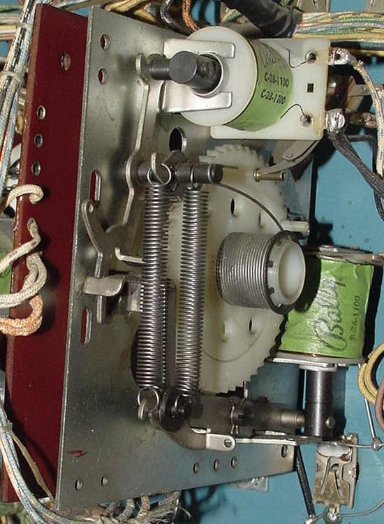
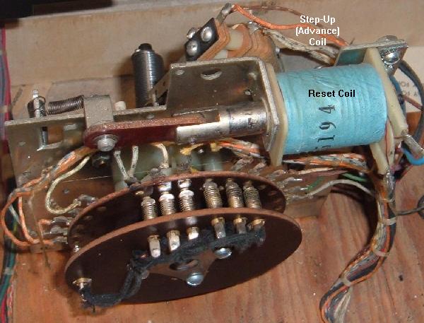
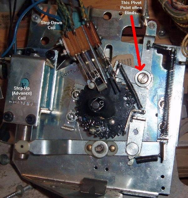
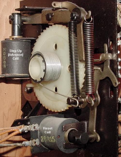
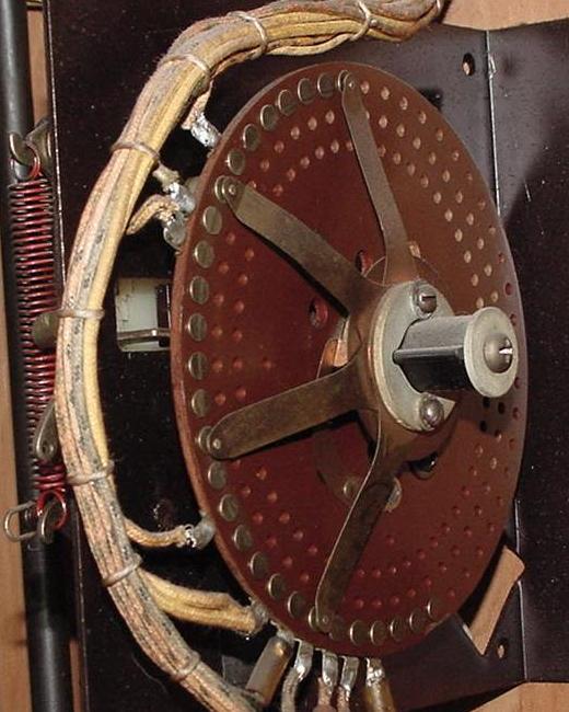
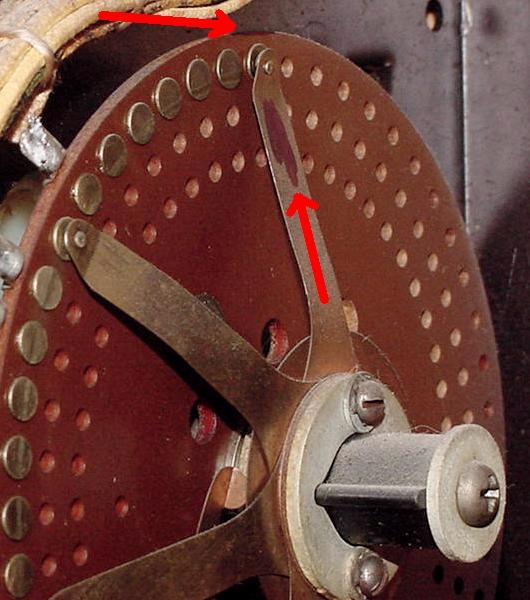
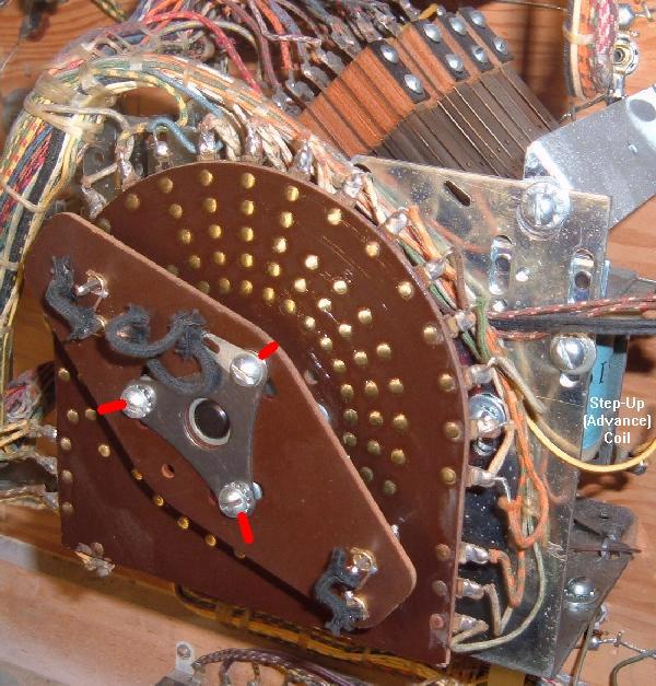
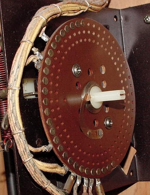
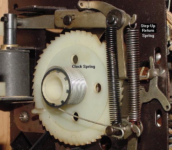
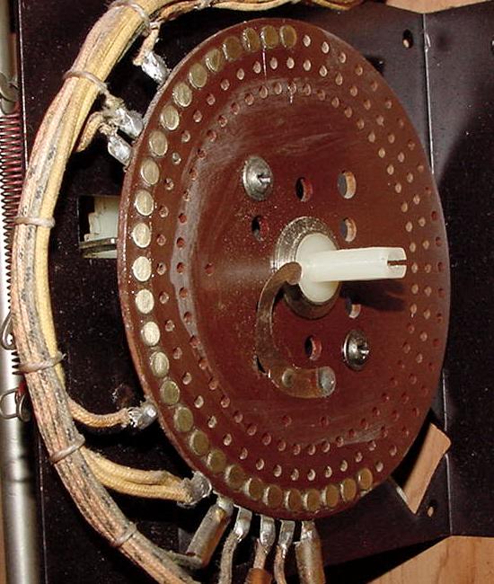
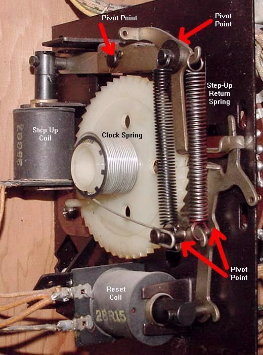
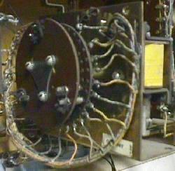
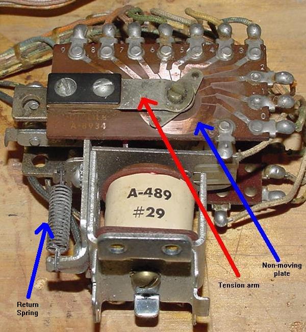
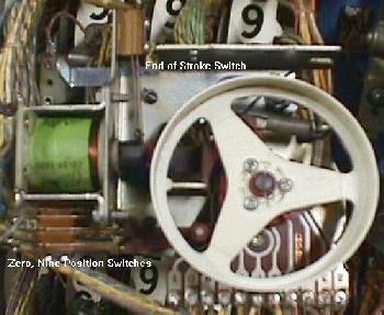
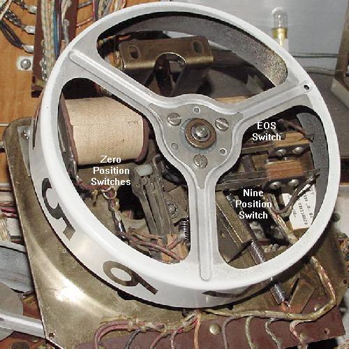
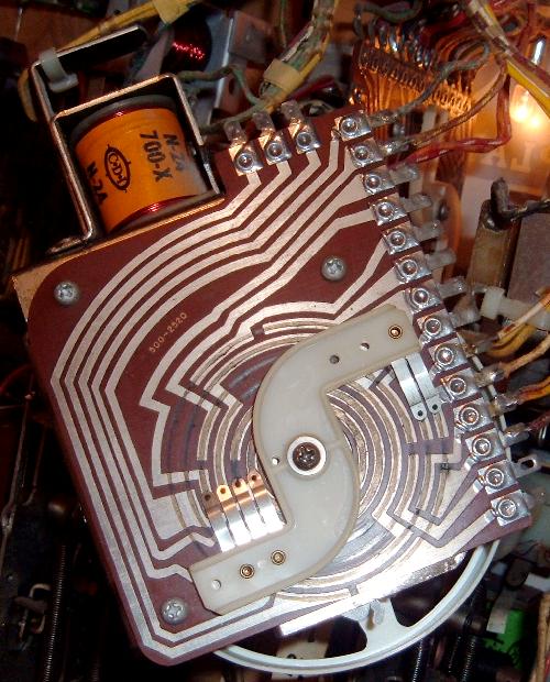
A common type of stepper unit is called the reset stepper, which uses two solenoids. One solenoid is known as the "step up coil", which advances the unit one position via a ratchet mechanism. This moves the wipers to the next set of contacts on the stepper. As the stepper increments, it winds a clock style spring tighter. Eventually the unit will come to some mechanical end, where it can no longer advance. There is also a second "reset coil" which releases the ratchet and resets the unit back to the "zero" position, regardless of its current position. Reset steppers are often used for scoring on games with no score reels (pre-1961). They are also used on newer style games as ball and bonus counters.
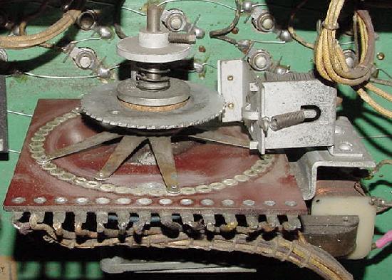
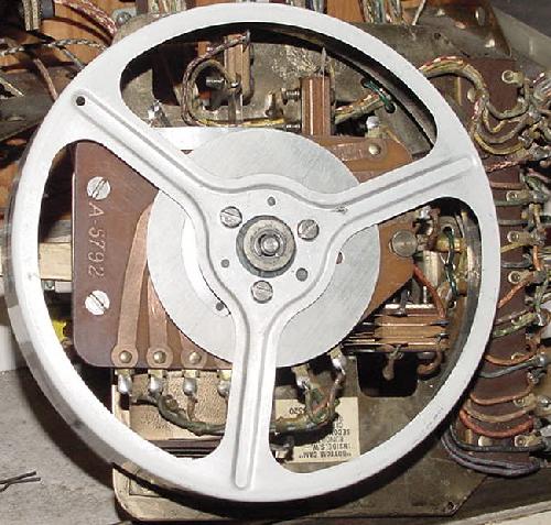
Yet another type of stepper unit is called a continuous stepper. These have just one solenoid, known as the "step up" coil. The only difference between the above reset stepper and the continuous stepper is the lack of a reset and there is no clock spring. To bring a continuous stepper back to the "zero" position means stepping through all its position to get back to zero. Continuous steppers are used where resets are not required, like in a "match unit". They were also used from pre-1961 as the low-score unit (the unit that kept track of the lowest score numbers in the game, like the 1000s or 10,000s). Another type of continuous stepper is the score reel (see the score reel section below for more information).
The last type of stepper is the increment/decrement unit. There are two coils on this unit, a "step up" coil and a "step down" coil. The step up coil works just like the other two steppers, using a ratchet mechanism to advance the stepper one position. But the step down coil also has a ratchet mechanism that decrements the stepper one position. A good example of the increment/decrement stepper is the credit unit.
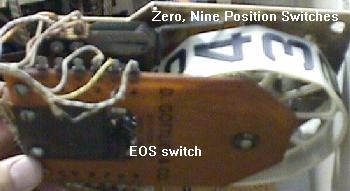
Most stepper units also use at least one End Of Stroke (EOS) switch for the stepper coils. When a stepper unit's solenoid energizes, this switch closes (or opens) as the coil plunger moves. Also most stepper units have some sort of zero position switch.
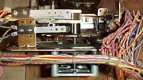
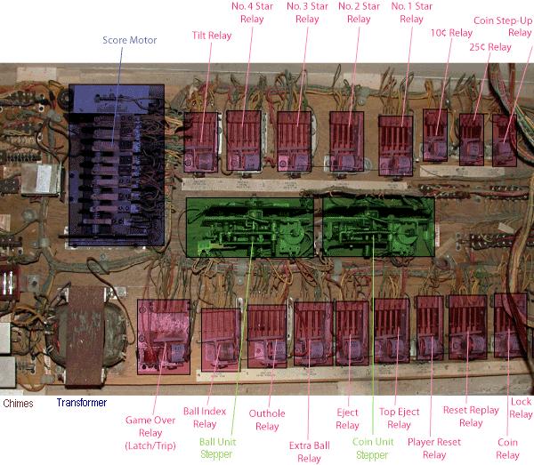
|
The bottom pannel of a 1970s Williams Grand Prix game. The coin door (front area) is to the left. Red shaded areas are relays, green shaded areas are Stepper units, blue shaded area is the Score Motor. Pic by Tor. |
|
Schematic Symbols.
-
At some point the schematics will need to be referenced when fixing a game.
The graphic below shows the most commonly used symbols on EM schematics, as
discussed above.
|
The most common schematic symbols used in EM games. |
|