|
1a. Getting Started: Experience,
What is WPC, Schematics
What Repair Experience Is Expected?
Little experience in
fixing pinballs is assumed. Basic electrical knowledge is helpful, but
not necessary. I do assume you can solder and use the basic features of
a Digital Multi-Meter (DMM) such as measuring voltage and resistance.
Please see ../begin
for details on the basic electronics skills and tools needed. This
document should help if you just bought your first (or second, or
third) Williams WPC pinball "as-is", and hope to fix it.
What is WPC?
WPC stands for "Williams Pinball Controller".
It is the internal pinball computer designed by Williams and used from
from late 1990 to 1999. Technically, the WPC chip is functioning as an
address decoder. It handles the I/O addressing (done previously with TTL
logic and 6821 PIA's on System 11), as well as system clocks, watchdog
reset, blanking, and real time clock. There are several generations of
WPC (see Different
WPC Generations).
Got Schematics?
Having a schematic for the game would be
ideal, but sometimes it can be fixed without it. If a schematic is not
available, order one from one of the suppliers on the parts and repair sources web page.
WPC Schematic Manuals.
Some 1991 and prior WPC games
(Gilligan's Island and before) have the backbox circuit board
schematics inside the game manual. For all other WPC games, the backbox
circuit board schematics (CPU, driver, sound and fliptronics) are in a
separate manual:
- Pre-DCS
(aka WPC-89, Funhouse to Twilight Zone): part number 16-9473
- WPC
DCS & WPC-S (Indiana Jones to Jackbot): part number 16-9834.2
- WPC-95
(Congo to Monster Bash): part number 16-10159.2
1b. Getting Started: Necessary Tools
Fixing electronic pinball games will require a few tools. Luckily,
most are not that specialized and are easy to get.
Non-Specialized Tools Required:
- Work Light: clamp style lamp
- Screwdrivers: small and medium size, phillips and flat head
- Nut Drivers: 1/4", 5/16", and 11/32"
- Wrenches: 3/8", 9/16", 5/8" required, other sizes suggested
- Allen Wrenches: get an assortment of American sizes
- Needle Nose Pliers
- Hemostat. Handy for holding parts and springs. Best to have both
the curved and straight versions if possible.
- Right Angled Screwdriver: both phillips and flat head.
Specialized Tools Required:
These specialized electronics
tools are needed. Please see ../begin
for details on the basic electronics tools needed.
- Alligator clips and wire. Buy these at Radio Shack, part number
278-001, $3.69.
- Soldering Iron.
- Rosin Core 60/40 Solder.
- De-soldering tool.
- Digital Multi-Meter (DMM).
- Logic Probe.
- Hand Crimping Tool: Molex WHT-1921 (part# 11-01-0015), Molex part#
63811-1000, Amp 725, or Radio Shack #64-410.
- Infrared Sensor. Used for determining good infrared optic LED's.
Radio Shack sells these for $5.99, part number 276-1099
Cleaning "Tools" Required:
- Novus #2 or MillWax (for cleaning playfields and rubber)
- Novus #3 (for polishing metal parts)
- A hard paste wax (like Trewax) or hard automotive Carnauba Wax
(for waxing playfields and cleaning rubber)
Novus is available
at many places (my local grocery store sells it), or from any good
pinball vendor. I don't recommend MillWax, but others like it (mostly
because they have been around for a LONG time and are used to it). Do
not use any Wildcat products! They react with acyrlic plastics, which
the playfield and ramps are coated. Trewax or Meguires Carnauba Wax is
available at Kmart or a local hardware store.
1c. Getting Started: Parts to Have On-Hand
1d. Getting Started: Different WPC
Generations
There are essentially six different generations of WPC systems.
Components and circuit boards change with each generation. Therefore it
is essential to know the game generation before starting repair.
- WPC Alpha-Numeric: used from Funhouse (10/90) to The
Machine BOP (4/91). This generation of WPC used 16 digit alpha-numeric
displays. These also used "normal" flippers, without a Fliptronics
board. Identified by no Fliptronics board in the upper left corner of
the backbox, and no dot matrix control board in the upper right side
of the backbox (some Dr.Dude games were also this WPC generation
although most were System11). All Dr.Dude WPC and early Funhouse games
used System11 sound boards.
- WPC Dot Matrix: used from Terminator2 (6/91) to Party Zone
(10/91). This generation of WPC used "normal" flippers, without a
Fliptronics board. Identified by no Fliptronics board in the upper
left corner of the backbox. Most Party Zone games don't have
Fliptronics boards, and fall into this category.
- WPC Fliptronics: Used from Addams Family (2/92) to Twilight
Zone (5/93). Some late Party Zone games also used this generation of
WPC. The Fliptronics (I) board used in Addams Family and Party Zone
are slightly different than all later Fliptronics II boards. The
difference being the addition of a bridge rectifier to the Fliptronics
II board for the flipper voltage.
- WPC DCS: Starting with Indiana Jones (10/93), Williams
upgraded the sound card to use "digitally compressed sound" (DCS) as
a different sound compression system. This gave much better sound and
more sound storage space.
- "WPC-89": All the WPC generations listed above are
generically grouped together and known as WPC-89 (initial design year
of 1989, opposed to WPC-95 which had an initial design year of 1995).
- WPC-Security (WPC-S): Starting with World Cup Soccer
(3/94), a security PIC chip was added to the CPU board in all WPC-S
games at location U22. This PIC (Programable Integrated Circuit) chip
was game specific. CPU boards can not be swapped between different
models of game without changing the security PIC chip (i.e. Corvette
CPU board put into a Shadow game must have the Corvette PIC changed to
a Shadow PIC chip). Each security PIC chip had a special serial number
encoded into the chip. This number displays on the dot matrix screen
for a few seconds as the game is turned on.
The number displayed shows what distributor the game was shipped to
from the factory. This was done by Williams because of problems in
Europe with distributors selling games outside of their sales
territory. Anyone could turn a game on, write down the displayed
serial number, and determine if the game was "bootlegged" from another
distributor. However, this was defeated by adding a dot matrix power
delay board. This small board didn't power the dot matrix display
until the game was turned on for about 10 seconds. This meant the
game was in attract mode (and the PIC number no longer displayed),
before the dot matrix display was even turned on. This was
embarrassing to Williams, as they spent much time and money to develop
the security PIC chip system as a distributor territory protection
device, yet the system was disabled by a simple modification. As a
backup, there is probably a set of "secret" flipper button codes that
will display the PIC number when the game is in attract mode (hence
getting around the DMD power delay).
Unfortunately for us, the PIC chip makes CPU repair more difficult,
as CPU boards can't be swapped between games without changing the PIC
chip. To make things worse, new PIC chips were available from Williams
for about $180 (retail) each. They were priced at this amount to deter
distributors who are bootlegging from purchasing additional PIC chips.
Now that Williams is out of the pinball business (as of Oct 25, 1999),
there are two companies making replacement PIC chips. In both cases
these new chips are a complete re-write of the original PIC code, so
there are no copyright or legal issues. They work with any version of
the game's CPU ROM code too. These new PIC chips are still game
specific, but for the price, they are a bargain. Available from Dave
Astill (no web page) and www.shiftedbit.com
(called "Ewe-22").
Williams manufactured and distributed a few redemption games during
the "FunHouse Games" label era (around 1992), including Screamin'
Slopes, Wheel of Fortune, and Real Monsters. They were designed and
programmed out-of-house, and have no WPC circuitry inside. The only
redemption pieces that used WPC hardware are Ticket-Tac-Toe and Addams
Family Values (Curiously, neither of those were marketed under the
"FunHouse Games" label).
- WPC-95: Starting with Congo (3/96) (and some Jackbot
games), Williams introduced a new WPC-95 CPU, driver board, and
audio/visual system. The Fliptronics board is now incorporated into
the driver board. The sound and dot matrix controller board are
combined into one board. WPC-95 also used a security PIC chip which is
at location G10. Most of the WPC-95 circuits are the same as WPC-S
and earlier. Exceptions include putting all the dot matrix display and
DCS sound driver logic into a single logic array chip (similar to the
WPC chip on the CPU board).
1e. Getting Started: Game List
Here are the list of WPC games and which generation they are. The
date indicated is the initial release date of the game (determined from
William's ROM code release dates, where available). Note that pre WPC-S
games are also known as "WPC-89" games (so the three main WPC
generations are WPC-89, WPC-S, and WPC-95).
WPC Alpha-Numeric
WPC-89 CPU board.
A-12738 sound
board
- Dr.Dude, 10/90 *
- Funhouse, 10/90 *
- Harley Davidson, 3/91
- The Machine BOP, 4/91
WPC Dot Matrix
WPC-89 CPU board.
A-12738 sound
board
- Slugfest Baseball, 6/91
- Gilligan's Island, 7/91
- Terminator2, 7/91
- Hurricane, 2/92
- Party Zone, 10/91 *
- Hot Shots (Basketball game)
WPC Fliptronics
WPC-89 CPU board.
A-12738 sound
board
A-15472 Fliptronics II board
- Party Zone, 10/91 *
- Addams Family, 3/92 **
- The Getaway, 4/92
- Black Rose, 8/92
- Fish Tales, 10/92
- Dr.Who, 10/92
- WhiteWater, 12/92
- Creature Black Lagoon, 1/93
- Dracula, 2/93
- Twilight Zone, 4/93 #
- Addams Family Gold, 7/94
WPC DCS
WPC-89 CPU board.
A-16917 DCS sound
board.
A-15472 Fliptronics II board
- Indiana Jones, 7/93 #
- Judge Dredd, 8/93 #
- Star Trek Next Generation, 11/93 #
- Popeye, 1/94 #
- Demolition Man, 4/94 #
- Addams Family Values (redemption).***
|
|
* These games share two different systems. Only about 100 Dr.Dudes
are WPC (most are System11). Early production Funhouse and all WPC
Dr.Dude games use System11 sound boards. Most Party Zone games are not
WPC Fliptronics (also a few Jackbot games were WPC-95. The sound ROMs
are different between WPC-S and WPC95 Jackbot, but the PIC and CPU ROMs
are the same).
** Addams Family only used a special Fliptronics I
board (but a Fliptronics II board can be used in these games). ***
Addams Family Values uses an A-12742 CPU and an A-16917 (DCS) sound
board, but the second sound amp (U27) and associated components (about a
dozen) are not populated on the sound board. Also AFV uses a compact
form factor version of the WPC power driver board A-17453, with a 8x8
lamp matrix, and provision for eight solenoid drives. Each solenoid
drive has a pre-driver and driver (TIP-102), and can also have a
high-power driver (TIP-36C) stuffed at each position. AFV is
configured with 7 general purpose and 1 high power solenoid drives. The
board does have connections for GI input and output, but there are no
TRIACs for dimming GI. The input and output connections simply loop
through their associated fuses.
Other Interesting Historical Tidbits.
The first dot matrix
Williams/Bally game released for sale was actually Slugfest in the
summer of 1991. Terminator2 was the first game designed with a dot
matrix display, but Slugfest and Gilligan's Island (which both had
shorter development cycles) beat T2 to market.
All games Gilligan's Island and later use "diamondplate" for the
playfield coating (though not all later games say "diamondplate" right
on the playfield). Diamondplate is a automotive style urethane coating,
which replaced Lacquer. Bride of Pinbot and early games used Lacquer
playfields, except for a few in each game title (mostly Pat Lawlor
games, since Pat was the one pushing Diamondplate) that were made with
Diamondplate. These early pre-Gilligan Island diamondplate playfields
are always labeled with a "Diamondplate" logo usually on the lower right
side of the playfield near the game credits. Banzai Run (system11) was
the first game (by Pat Lawlor) where diamondplate was tried.
Most WPC games use a "translight" (a plastic film) for the backglass
artwork. Therer are a few exceptions. No Good Gofers and Champion Pub
used a "real" backglass with artwork screened directly onto the
tempered glass. Cirqus Voltaire uses a screened acrylic backglass that
covers the full area of the backbox. It has speaker grill slots cut
into the plastic at the lower left and right corners.
Playfield Glass Size.
All pinball playfield glass is
"tempered" glass. Do NOT use "plate" glass in a pinball game!
- All the above games (except where noted below) use the standard
glass size of 21" x 43" x 3/16". This size was used on most pinball
games from the 1950's through WPC.
- # - These games are "super-pins" with wide playfield bodies. These
use 23.75" x 43" x 3/16" tempered playfield glass.
- Safe Cracker and Ticket Tac Toe used 18.5" x 36.5" x 3/16"
tempered playfield glass.
- Slug Fest, a WPC pitch and bat game, uses 23" x 35 1/4" x 3/16"
tempered playfield glass.
The size of the glass covering the translight on nearly all WPC games
is 18 7/8" x 27" (Safe Cracker uses 18 7/8" x 19 1/2). The glass
thickness is what most hardware stores call "double thick" glass, which
is about 1/8" thick. Tempered glass can be used for the translight, but
really it is not needed there (unlike playfield glass which must be
tempered!) Note backglass assemblies changed with WPC-95, when Williams
changed to the "light tub" to hold the backbox lighting. The translight
channels are wider than previously used. WPC-95 translight lift channel
part numbers are WLL-03-9420 for the bottom lift channel, WLL-03-9421-1
for the top channel, and WLL-03-9421-2 for the (2) side channels.
Leg Color.
Most WPC Bally/Williams games use chrome legs,
but there are some exceptions. Corvette, Dr.Who, Harley Davidson, Black
Rose, Star Trek Next Generation and Party Zone (and also all Pinball
2000 games) used black legs. Creature from the Black Lagoon uses very
dark (gun metal) grey legs (almost black, but not quite). Corvette used
black legs and black metal side rails and lockdown bar, and was the
only Bally/Williams WPC game to have that. Roadshow used blue legs (and
early "sample" games used a blue lockdown bar too). A few games used
gold anodized legs, including Indiana Jones, Flintstones, Addams Family
Gold, World Cup Soccer and Judge Dredd. All other games not mentioned
above used chrome legs.
1f. Getting Started: Lubrication Notes
Pinball machines, for the most part, do not require any
lubrication. Most parts run "dry". Far more damage can be done to a
pinball machine by over-lubricating, than by under-lubricating. As a
rule, if in doubt as to lubrication, don't do it! Throw that WD-40 away,
it won't be used here.
The only parts that will require any lubrication are metal-to-metal
moving parts. There aren't very many in a game. Only ball eject and
slingshot hinges. Use 3-in-1 oil on these if you must. But try and keep
that lubrication in the tool box and away from the game.
If some prior person did lubricate the game, the lubrication has
probably now congealed with the infamous "black pinball dust" to form a
thick, black mess. This is unrepairable on coil sleeves, and new parts
will need to be installed.
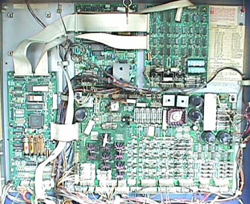
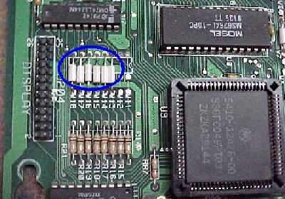
1g. Getting Started: The Circuit Boards
(Generations)
There are basically three main WPC generations: WPC-89, WPC-S, and
WPC-95, with WPC-89 have several sub-generations. Some boards are
interchangable between games and systems, some are not.
The back
box in a 1991 Bally Gilligan's Island (second generation
WPC-89).
The CPU board is on the far left. The driver board is
the largest board,
and occupies the lower right area. The sound
board is at the upper middle.
The dot matrix controller board is
at the upper right. The "missing"
board (upper left) is where
the Fliptronics board will be located on 1992
and later games.
Note the four mounting posts for this missing Fliptronics
board.
Newer Fliptronics II boards use six mounting
posts.
|
|
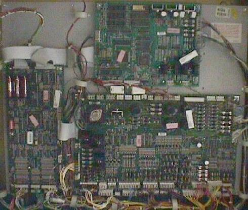
WPC-95
boards. Note fewer number of boards in WPC-95. The Fliptronics
board is now incorporated into the Driver board. The dot matrix
controller
board and the sound board are combined into one board
called the "A/V board". |
|
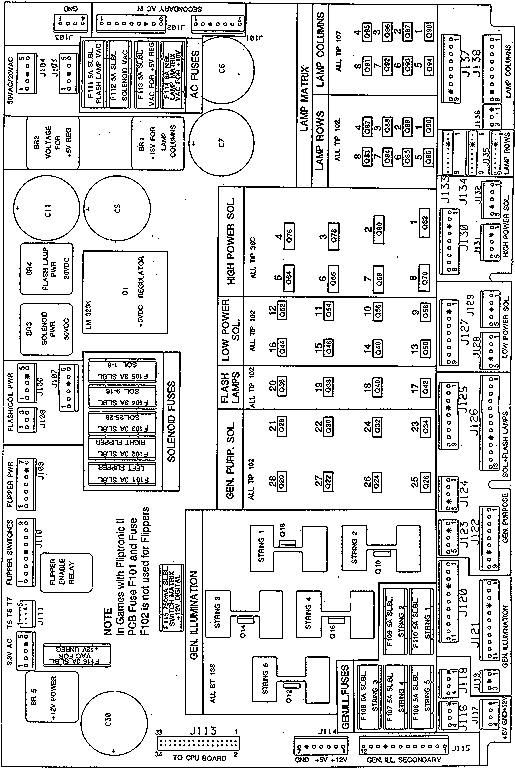
WPC Power Driver Board.
Most of the repair work will
probably relate to this board. The more familiar one is with the Driver
board, the better they will be able to fix WPC games. The driver board
drives all solenoids and lamps. It provides the power for almost all the
parts of a WPC pinball game. It houses most of the fuses too.
A drawing
showing the usage of the connectors, fuses and transistors on a
WPC-S and prior Driver board.
|
|
Board Generations.
Note the following "A" numbers for each
WPC board are NOT printed on the boards themselves. The "A" numbers are
from the game manuals, and are known as the "assembly" numbers. Often
the "A" number is on a sticker stuck on the component side of the
board. The second number (in parends) starting with "5" is the bare
board part number (no part installed). This number IS printed on the
solder side of the board itself. It is possible to swap some boards
between WPC games.
CPU board.
- A-12742-gamenumber (5764-12431-00): non-security WPC-89 version
used from Funhouse to Popeye. Swappable between these games only
providing the correct game EPROM is used (early versions of this
board need a jumper change to convert from a 512k 27512 or 1meg
27010, to a 2meg 27020 or 4meg 27040 game EPROM). This is also
known as a WPC-89.
- A-17651-gamenumber: WPC-S (security) version used from World Cup
Soccer to WhoDunnit. Swappable between these games only, providing
the correct PIC security chip and game EPROM is used.
- A-20119-gamenumber: WPC-95 CPU board. Can be used on any WPC-95
game from Congo to Cactus Canyon, providing the correct PIC security
chip and game EPROM is used. A-21377-gamenumber (5764-14823-0). Can
also be 04-12358 (same as A-21377 but without the game specific
chips). There is also a A-21369 version that uses a different RAM
chip. These are all interchangable among WPC95 games. Can be used
on any WPC-95 game from Congo to Cactus Canyon, providing the
correct PIC security chip and game EPROM is used.
CPU boards are not interchangable between different WPC generations
(that is, a WPC-95 CPU board can not be used in a WPC-89 game).
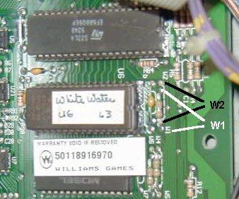
CPU Board EPROM Size Jumpers (W1/W2).
On pre WPC-S CPU
board A-12742, there are two jumpers that relate to the size of the U6
EPROM. In most cases, these jumpers will not need to be changed. Only
on very early WPC games using smaller 1meg EPROMs (Funhouse, Harley
Davidson, Bride of Pinbot) this can be a problem. For example, if a
Funhouse game is running the original first version of software (using
a 1meg 27010 EPROM), and then is upgraded to the latest vesion (using
a 2meg 27020 EPROM), the jumpers will need to be changed. Or if an
original Funhouse CPU board is used in a later game using a 4meg 27040
EPROM, the jumpers will also need to be changed.
Both of these jumpers are located to the right of the U6 game ROM
chip, when looking at the board as mounted in the backbox (see
below). A jumper is basically a wire that connects two points on the
board. The CPU board jumper labels are located in between two points,
with dotted lines outlining the two points to jumper. The jumper may
be just a simple bare wire, or a wire with white ceramic insulator
around the middle of it, or may look like a (zero ohm) resistor. A
connection between either set of two points is considered "In". A set
of two points that doesn't have a connection between them is
considered "Out". A soldering iron is required to change these
jumpers. Here is the jumper chart:
| Pre WPC-S CPU Board EPROM Jumpers |
| EPROM
Size
| Jumper
W1
| Jumper
W2 |
|
1meg (27010) |
OUT |
IN |
|
2meg (27020) |
IN |
OUT |
|
4meb (27040) |
IN |
OUT |
On pre
WPS-S CPU boards, shown are the W1 and W2
EPROM size jumpers
to the right of the U6 chip. This
game is set for a 27020 or
27040 EPROM.
|

|
On some schematics, the W1/W2 jumpers are shown to indicate the
type of display used (alpha-numeric, or dot matrix). A dot matrix
display is shown as W1=in, W2=out. An alpha-numeric display is shown
as W1=out, W2=in.
CPU Board Country Jumpers (W15-W18).
On pre WPC-S CPU
board A-12742, there are four jumpers that relate to the country of
usage for the game. These jumpers will determine the default
language, game rules and coinage for the game, and are located to the
left of the large square U9 chip. If a WPC game is imported back to
the USA, I would highly suggest converting the jumpers to America2 or
America language settings. This way if the batteries die, the game
will boot up in English instead of say German.
As described above for the EPROM size jumpers, the jumper may be
just a simple bare wire, or a wire with white ceramic insulator around
the middle of it, or may look like a (zero ohm) resistor. It could
also be a DIP switch too (Williams started using DIP switches for
these jumpers somewhere around Star Trek Next Generation). A
connection between either set of two points is considered "In". A set
of two points that doesn't have a connection between them is
considered "Out". A soldering iron is required to change these jumpers
if there is no DIP switch.
The inside front page of the game's operating manual should
identify exactly how jumpers W15-W18 should be set. Note W13 and W14
should always be IN (set) regardless of the country setting. If the
W15-W18 jumpers are set to an unknown setting, the game can exhibit an
error on the score display which say (for example), "country code
must be specified using jumpers W15-W18. Cut W15,W16,W17,W18 for USA".
This is most often seen on Twilight Zone (which seems to prefer the
America2 setting with W15-W18 removed). Again confirm the exact
setting in the game manual. Shown below is a typical chart for this
(though it can vary from game to game).
On imported/exported WPC games from other countries I generally
remove W15-W18 for "America2" as this is an English language default.
It is a lot easier to cut jumpers than it is to add them back! There
is always potential for board damage when soldering jumpers, so
removing W15-W18 is definately the easiest way to make a game default
to North American English standards.
|
Typical Pre WPC-S CPU Board Country Jumpers |
| Country |
Jumper
W13 |
Jumper
W14 |
Jumper
W15 |
Jumper
W16 |
Jumper
W17 |
Jumper
W18 |
| America2* |
In |
In |
Out |
Out |
Out |
Out |
| America |
In |
In |
In |
In |
In |
In |
| Spain |
In |
In |
Out |
In |
In |
In |
| Europe |
In |
In |
In |
Out |
In |
In |
| French |
In |
In |
In |
In |
Out |
Out |
| German |
In |
In |
In |
In |
In |
Out | * Some
games use the "America2" settings instead of the "America" settings.
But either America or America2 is a good setting for WPC games in
North America.
On pre
WPS-S CPU boards, shown are the W18 to W13 (left to
right)
country jumpers to the left of the large square U9 chip.
W13-W18 are "in", so this games is set for
"America".
|
|
For WPC-S and WPC-95, Williams changed to a eight position DIP
switch block for country of usage. This requires no tools to change
the jumper seetings. Here are the typical settings (again confirm the
settings with the owners manual):
| WPC-S/WPC-95 CPU Board Country Jumpers |
| Country |
SW1 |
SW2 |
SW3 |
SW4 |
SW5 |
SW6 |
SW7 |
SW8 |
|
America |
Off |
Off |
On |
On |
On |
On |
On |
On |
|
Europe |
Off |
Off |
On |
On |
On |
Off |
On |
On |
|
French |
Off |
Off |
On |
On |
On |
On |
Off |
Off |
|
German |
Off |
Off |
On |
On |
Off |
On |
On |
On |
Transformers.
All pre WPC-S games have the transformer
near the front coin box area of the lower cabinet. With WPC-S, the
transformer moved to a mounting plate on the back of the lower
cabinet. The second generation WPC-95 transformers are a bit smaller
than earlier WCP-95 models having wider mounting brackets (hence
"wide mount"). Across all the WPC machines, the output connections are
the same, which is dangerous since all WPC transformers are not
interchangable. DCS WPC games definately need a different transformer
than non-DCS games, as the sound board requires different unregulated
voltage.
- 5610-12835-00: Installed in alpha-numeric WPC and pre-DCS dot
matrix games including Black Rose, Dracula, Bride of Pinbot,
Creature, Dr.Who, Funhouse, Fishtales, Gilligan, Harley Davison,
High Speed2, HotShots Basketball, Hurricane, Party Zone, Slugfest,
Terminator2, Addams Family, Twilight Zone, Whitewater.
- 5610-13491-00: Used in WPC-89 games with DCS sound and the
transformer mounted by the coin box including Indy Jones, Demo Man,
Judge Dredd, Pinball Circus, Popeye, Star Trek Next Gen.
- 5610-13953-00: Used in WPC-S games with DCS sound with the
transformer mounted at the lower cabinet's back including Corvette,
Dirty Harry, Flintstones, Roadshow, Shadow, World Cup Soccer.
- 5610-14515-00: WPC-95 transformer (not wide mount)
- 5610-14515-01: Second WCP-95 transformer with wide mount
- 5610-15930: Pinball 2000 transformer
Driver board.
- A-12697-1 (5763-12405-00): the driver board used from Funhouse to
the middle production of Twilight Zone. It has a flipper enable relay
on the board. Can be used on all WPC games from Funhouse to WhoDunnit
(the most versatile non-WPC95 driver board, can be used in any WPC-89
or WPC-S game). On Fliptronic games (Addams Family and later), the
flipper relay is ignored by the game's software.
- A-12697-3: Used starting mid-production of Twilight Zone. The
flipper enable relay is not installed (since these games have
Fliptronics boards, and no long need the relay). Can be used on Addams
Family to WhoDunnit. Can *not* be used on Funhouse to Hurricane
because of the lack of the flipper relay, which is needed in
non-fliptronic games (games prior to Addams Family).
- A-12697-4: One of the solenoid fuses changef rom 3amp to 5 amp,
removed the "line level circuitry" (around U6). WPC Schematic Manual
16-9834.2 details these changes on page 1 of the power driver board
schematics. The specific components are R1, R2, R3, R4, R5, R6, R195,
R200, F201, W1, W2, LED2, and LED3. Can be used on Addams Family to
WhoDunnit (interchangable with the -3 revision). Only used on a one
game (just WhoDunnit so it seems). Thanks Tony.
- A-20028 (5763-14525-06): WPC-95 only driver board. Can be used on
Congo to Cactus Canyon only.
The first generation driver board
A-12697-1 is the most versatile, and can be used on all non-WPC95 games.
Sound board.
- A-12738-gamenumber: analog/digital hybrid. Can be used on Funhouse
to Twilight Zone, providing the correct sound EPROMs are used.
- A-16917-gamenumber: DCS sound board with pure DSP generated
digital sound. Can be used on Indiana Jones to WhoDunnit, providing
the correct sound EPROMs are used.
- A-20516-gamenumber (5760-14495-10): WPC-95 only sound/audio visual
board. Can be used on Congo to Cactus Canyon only, providing the
correct sound EPROMs are used.
Sound boards are not
interchangable between different WPC generations. Also each game uses
its own Sound ROMs, which would need to be changed if a board is swapped
from game to game (or your Addams Family could be playing Funhouse
sounds!) Within a generation, there can be some minor differences
between sounds boards too. For example, the sound board on Funhouse has
some different resistor values than the sound board on Addams Family to
vary the sound level for voice and background sound (though they are the
same sound board, and are interchangable). More information on this can
be found here.
Display board.
- A-12739-1: Alphanumeric WPC Display Driver board, from Funhouse to
the Machine BOP.
- A-14039 (5760-12710-00 REV 6): Dot matrix, from Terminator2 to
World Cup Soccer (at least this is what the game manuals indicate).
Infact, this board was really used from Terminator2 to Popeye (all
pre WPC-S dot matrix games).
- A-14039.1 (5760-12710-12): Dot matrix, from Flintstones to
WhoDunnit (at least this is what the game manuals indicate). Again
infact, this board was actually used from World Cup Soccer to
WhoDunnit (all the WPC-S games).
- WPC-95 did not use a separate display board, hence games Congo to
Cactus Canyon do not need this board (display is handled by the WPC-95
A-20516-(game number) "audio-visual" board).
Note
"5760-12710-00 REV 6" and "5760-12710-12" are completely interchangable
and plug compatible. The only difference in the newer -12 board is the
additon of a 74HCT138 chip at location U12 (between U11 and U34). The
older -00 board has a spot for this chip on the board, but the chip is
not installed (and no, the chip can not be added to upgrade a -00 board
to a -12; other changes must also be made). Apparently there was a
problem caused by new (internally smaller die size) parts such as RAM
and support glue logic. This brought up a race condition that had been
overlooked in the original "REV 6" design. If repairing an older "REV
6" board with newer parts, it could show some problems (wandering
and/or flickering dots on the display).
WPC-95 A/V Board.
- 04-12357-2: This is apparently an A-20516 without game-specific
chips. There is also an A/V board with part number A-20145-2. These
are all interchangable.
Fliptronics board.
- A-15028: Flipper Controller Assembly (Fliptronics I), used on
Addams Family only. Can not be used on any other game.
- A-15472: Fliptornics II board, used from Getaway to Twilight Zone.
Fliptronics II adds a bridge rectifier to the circuit (interchangable
with A-15072-1).
- A-15472-1: Fliptornics II board, used from Indiana Jones to
WhoDunnit. The only difference between this and A-15472 is the 50 volt
filter capacitor for the flipper power was removed (interchangable
with A-15072).
- WPC-95 did not use a separate Fliptronics board, hence games Congo
to Cactus Canyon do not need this board.
Flipper Opto board.
Starting half way through the
production of Addams Family, Williams started using a flipper opto board
instead of leaf switches for the flipper cabinet switches. Each flipper
opto board (there are two, one for each flipper cabinet switch) holds
two, 4-leg "U" shaped optics. The board has one optic for the lower
flipper, and one for the upper flipper (even if the game only has two
lower flippers). Starting with WPC-95, the "U" optic changed to a five
leg opto (known as a Schmitt trigger opto). These newer five leg optos
has less problems with dust and intermittent operation. Either opto
flipper board can be used and interchanged amoung any game using
flipper cabinet opto switch boards.
- A-17316 (5768-13469-00): WPC-S and prior 4-leg "U" opto flipper
cabinet switch board.
- A-20207.1 (5768-145-8-00): WPC-95 5-leg "U" opto flipper cabinet
switch board.
1h. Getting Started: Introduction to
Operation
Much technical information in this section. If this makes you
uncomfortable, please skip. This info is provided for completeness. You
don't need to understand it to repair a WPC game. All the connector/chip
numbers listed below are for WPC-S and prior games (though this
information generally applies to WPC-95 too).
Connector, Fuse and Board Numbers.
Every plug has a number
that identifies the circuit board and position on the board that it
connects to. For example, J101 designates board 1, jack 1. Identifying
the pin number of a connector involves a hypen. For example, J103-5
means board 1, jack 3, pin 5.
Fuses are also identified in this manner. For example, F501 means
board 5, fuse 1.
Prefix number for WPC boards:
- 1 = Power driver board
- 2 = CPU board
- 3 = Display driver board
- 4 = Dual or single display board
- 5 = Sound board
- 6 = Dot matrix controller board
- 7 = Printer kit boards
- 9 = Fliptronics board
Circuit Board Descriptions.
- CPU board: The CPU board uses a 68B09E microprocessor and controls
all logic and switch functions.
- Power Driver Board: Does not contain any game specific components.
Contains the lamp, general illumination (GI), flipper
(pre-fliptronics) and solenoid circuits. Also supplies +18 volts for
the lamp circuits, +50 volts for the solenoids, +5 volts for the logic
circuits, +12 volts for the switch circuits, and 6.3 volts for the
general illumination circuits. Not game specific.
- Display Driver Board: part number A-12739. Used on pre-dot matrix
WPC games. The hyphen after the part number indicates how many
extended displays are used. No extended display is "-1", one extended
display is "-2", and two extended displays is "-3".
- Single Display Board: part number A-12794. Used on pre-dot matrix
WPC games, and contains one 16 digit alpha numeric display glass.
- Dual Display Board: part number A-12793. Used on pre-dot matrix
WPC games, and contains two 16 digit alpha numeric display glass.
- Dot Matrix Controller Board: supplies the data for the dot matrix
display to operate. Not game specific.
- Dot Matrix Display/Driver Board: contains the dot matrix glass and
driver board. Not game specific.
- Sound Board: produces all speech and music.
CPU Board Operation.
CPU board performs two main
operations: logic and switch control.
- Microprocessor (U4): uses a 68B09E to control and process data.
The "B" and the "E" designations are required for WPC games (that
is, a 68B09 or 6809E will not work in WPC games). With an
oscilloscope, the address and data lines should be square waves with
at least 4 volts peak to peak. The processor runs at 2 mHz clock
supplied by pins 81, 82 of the ASIC. Pins 34, 35 of the processor
should be square waves, at least 5 volts peak to peak. Reset (pin 37),
IRQ (pin 3), and R/W (pin 32) should also be at least 4 volts peak to
peak during normal operation.
- ROM (U6): uses a 1 meg to 8 meg EPROM which contains the game
program. Using an oscilloscope, the address and data lines should be 4
volts peak to peak square waves.
- RAM (U8): uses a 2064 CMOS RAM which store game specific audit
information and adjustment settings. The battery circuit is connected
to the cathodes of D1 and D2, which connect to U8 pins 26 and 28. When
the game is on, pins 26/28 should have +5 volts peak. When the game is
off, pins 26/28 should have at least +4 volts as supplied by the
battery. If this drops below +4 volts, memory reset will occur.
- ASIC (U9): stands for Application Specific Integrated Circuit.
This chip handles the address decoding, system timing, a real time
clock, and system sequencing. Using an oscilloscope, the address and
data lines should be at least 4 volts peak to peak. The other pins on
this chip should have either a solid high or solid low with nothing
floating. This chip is not game specific, but is specific to WPC.
Provides two clocks (real time and system timing). The blanking
circuit is monitored by the ASIC. Blanking is active during power on
until the microprocessor is running, and has reset the latches to the
normal operating modes. This prevents coils or motors from energizing
when the game is turned on. Once the microprocessor has reset the
latches blanking becomes +5 volts level.
- Miscellaneous Buffers/Latches (U1, U2, U3, U5, U7, U12, U21): used
as temporary memory storage for the microprocessor. Address and data
lines should be 4 volts peak to peak. Any address or data lines that
are not pulsing should have a solid high or low, nothing floating.
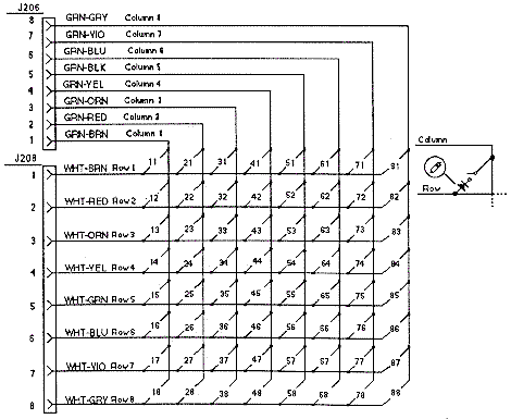
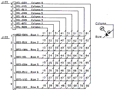
| Switch Matrix (all WPC games) |
Dedicated
Grounded
Switches |
Column/
Row |
1
Green-
Brown |
2
Green-
Red |
3
Green-
Orange |
4
Green-
Yellow |
5
Green-
Black |
6
Green-
Blue |
7
Green-
Violet |
8
Green-
Gray |
D1
Orange-Brown
Left Coin Chute |
1
White-
Brown |
11
Right
Flipper |
21
Slam
Tilt |
31 |
41 |
51 |
61 |
71 |
81 |
D2
Orange-Red
Center Coin Chute |
2
White-
Red |
12
Left
Flipper |
22
Front
Door |
32 |
42 |
52 |
62 |
72 |
82 |
D3
Orange-Black
Right Coin Chute |
3
White-
Orange |
13
Start
Button |
23
Ticket
Dispenser |
33 |
43 |
53 |
63 |
73 |
83 |
D4
Orange-Yellow
4th Coin Chute |
4
White-
Yellow |
14
Tilt
Plumb |
24
Test
Position |
34 |
44 |
54 |
64 |
74 |
84 |
D5
Orange-Green
Service Credits |
5
White-
Green |
15 |
25 |
35 |
45 |
55 |
65 |
75 |
85 |
D6
Orange-Blue
Volume Down |
6
White-
Blue |
16 |
26 |
36 |
46 |
56 |
66 |
76 |
86 |
D7
Orange-Violet
Volume Up |
7
White-
Violet |
17 |
27 |
37 |
47 |
57 |
67 |
77 |
87 |
D8
Orange-Gray
Begin Test |
8
White-
Gray |
18 |
28 |
38 |
48 |
58 |
68 |
78 |
88 |
- Switch Circuit: operates on +12 vdc. Most switches are tied
to a column and row circuit. Some switches are "dedicated" and their
curcuit is tied directly to ground through a switch. Playfield and
cabinet switches make up the matrix, while the coin door makes up the
dedicated switches.
Switch
Matrix circuit.
|
|
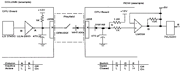
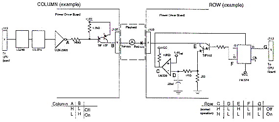
- Switch Matrix Circuit: microprocessor constantly strobes
the column side of the switch matrix. When the ULN2803 (column)
toggles low from a switch closure, the column is active.
When a switch closes, point C on the row circuit drops low, This
causes the "+" input to the LM339 to go below +5 volts so point D is
low, and the row is active. When corresponding row and column switch
are low at the same time, the switch circuit is active and is
registered as closed by the microprocessor. When the switch opens,
point C on the row circuit is high, and the "+" input to the LM339 is
at +5 volts. This makes point D high, and row is inactive.
Switch
Matrix rows and columns.
|
|
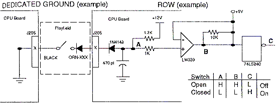
- Dedicated Switch Circuit: these switches have a similar
circuit as the matrix row switches. The dedicated switches include the
coin door test buttons and coin switches. These are separate from the
switch matrix because if a playfield switch problem occurs and blows
the entire switch matrix, the dedicated coin door diagnostic switches
should still work allowing the game to be tested. The dedicated
switch circuit operates the same as in the switch matrix circuit. When
a dedicated switch is closed, the circuit is driven low. Since the
other side of the switch is tied to ground, the microprocessor
recognizes the switch as being closed.
Dedicated
Switch.
|
|
- CPU Power Circuit: the power for the CPU board is supplied
from the Power Driver board. The input +12 and +5 volts DC are on
connector J210.
Power Driver Board.
The lamp, solenoid and general
illumination (GI) circuits are driven from this board. The control for
these circuits is provided by the CPU board.
| Lamp Matrix (all WPC games) |
Column/
Row |
1
Yellow-
Brown |
2
Yellow-
Red |
3
Yellow-
Orange |
4
Yellow-
Black |
5
Yellow-
Green |
6
Yellow-
Blue |
7
Yellow-
Violet |
8
Yellow-
Gray |
1 Red-
Brown |
11 |
21 |
31 |
41 |
51 |
61 |
71 |
81 |
2 Red-
Black |
12 |
22 |
32 |
42 |
52 |
62 |
72 |
82 |
3 Red-
Orange |
13 |
23 |
33 |
43 |
53 |
63 |
73 |
83 |
4 Red-
Yellow |
14 |
24 |
34 |
44 |
54 |
64 |
74 |
84 |
5 Red-
Green |
15 |
25 |
35 |
45 |
55 |
65 |
75 |
85 |
6 Red-
Blue |
16 |
26 |
36 |
46 |
56 |
66 |
76 |
86 |
7 Red-
Violet |
17 |
27 |
37 |
47 |
57 |
67 |
77 |
87 |
8 Red-
Gray |
18 |
28 |
38 |
48 |
58 |
68 |
78 |
88 |
- Feature Lamp circuit: To turn a lamp on, the processor
sends a signal to the ULN2803 causing the output (point A) to toggle
low. This causes the TIP107 transistor to conduct +18 volts, and it's
output (point B) to go high. At the same time, the CPU board (point G)
drops the output of a 74LS74 (point F) to go high. This causes the
TIP102 transistor to conduct and the collector of the TIP102 (point E)
to go low. When there is a high state on the TIP107 (point B) and a
low stated on the TIP102 (point E), this completes the circuit to a
lamp and the lamp lites.
The microprocessor shuts off the lamp circuit by changing point G
to high. However, in overcurrent conditions the lamp circuit is shut
off through the comparator (this is known as "strobing"). While the
lamp is on, the .2 ohm resistor acts as a current sensor and the 1k
ohm resistor and .22 mfd capacitor act together as a filter. These
components monitor the row circuit and send a voltage signal to the
input of the LM339 (point D). If the voltage at point D rises above
1.4 volts the output of the LM339 (point C) goes low, which is fed
back to the 74LS74 and shuts the row circuit off. Once the row is shut
off through the comparator, the processor must signal the 74LS74 to
enable the row circuit again.
Lamp
matrix circuit.
|
|
Lamp
matrix rows and columns.
|
|
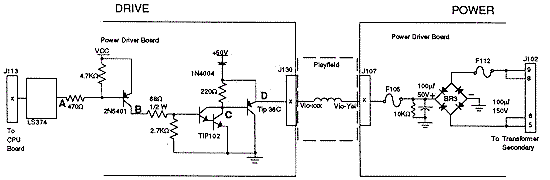
- Solenoid circuits: there are four types of solenoid
circuits. High power, low power, flashlamp and general purpose. Most
solenoids are pulsed (pulsed power output). Some solenoids are left on
(relays and motors) for a specific time.
- High power solenoids: operated from +50 volts unregulated
power and generally use a AE-26-1200 coil. This circuit contains a
TIP36 driver transistor and a 1N4004 tieback diode to dissipate the
coil induced voltages. Solenoids 1 to 8 are high power solenoids.
The microprocessor toggles the output of a 74LS374. When the
74LS374's output (point A) drops low, the collector of the pre-driver
2N5401 (point B) is high. This causes the collector of the TIP102
(point C) and the emitter of the TIP36 (point D) to drop low. This
grounds the coil and the coil is turned on. The coil shuts off when
the output of the 74LS374 (point A) goes high.
High
Power Solenoid Circuit
|
|
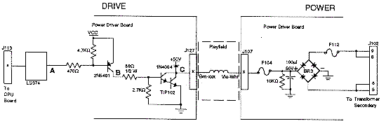
- Low power solenoids: operated from the same +50 vdc
unregulated power supply as the high power solenoids. This circuit
generally uses a AE-26-1500 coil and has a tieback diode to dissipate
the coil enduced voltage. Solenoids 9 to 16 are low powered and use a
TIP102 driver transistor.
The microprocessor toggles the output of a 74LS374 (point A) low,
which makes the pre-driver 2N5401 collector (point B) go high. This
causes the TIP102 collector (point C) and go low. This turns on the
ground for the coil, which turns the coil on. The coil is shut off
when the 74LS374 (point A) goes high.
Low Power
Solenoid Circuit
|
|
Flashlamp
Circuit
|
|
- General purpose Coils: these are a cross between the low
power coils and flashlamps. The tieback diode is optional and
determined by the wiring harness. If the general purpose solenoid is
used as a coil driver, the diode is connected to +50 volts. If the
general purpose solenoid is used as a flashlamp, the circuit operates
+20 unregulated volts DC and the tieback diode is not connected.
Solenoids 21 to 28 are the general purpose solenoids.
As with the other solenoid circuits, the microprocessor toggles
the output of a 74LS374 (point A) low. This turns on the pre-driver
2N5401 and the collector (point B) goes high. This causes the TIP102's
collector (point C) to go low and complete the ground for the
flashlamp or coil. When the 74LS374 (point A) goes high, the circuit
shuts off.
General
Purpose Solenoid Circuit. Tieback diode (next to point C) not
used
when flashlamp is driven.
|
|
- General Illumination (GI): contains five separate strings
of up to 18 bulbs per string, with a maximum of 90 bulbs. The circuit
uses 6.3 AC volts, which comes from the transformer, to the power
driver board, through a fuse, through a Triac (except for two strings
in WPC-95), and to the playfield. The five strings are controlled by a
Triac (except on WPC-95, where only three strings are Triac controls
and two are static), and the Traics are controlled by the
microprocessor. The microprocessor does this through through a latch
that it uses to store control signals.
The Triac-controlled GI strings can be dimmed. The microprocessor
has the ability to know when the AC line voltage is passing through a
zero cross. Dimming is achieved by the microprocessor sending a
control signal to the 74LS374 latch, which turns the triac on after
the zero cross has been detected. The longer the delay, the dimmer the
bulbs. This dimming effect is known as 'duty cycling' the triacs/lamp
strings at different frequencies. The trigger event for the timing is
the zero-crossing circuit (which switches 120 times per second as the
AC wave passes through zero volts).
To turn the bulbs on without dimming the microprocessor sends a
control signal to the triac, and leaves the signal applied. When the
74LS374's output (point A) goes low, the collector of the 2N4403
(point B) and the triac (point C) go high. This turns the triac on,
which turns on its general illumination string.
General
Illumination (GI) circuit.
|
|
- Flipper Circuit: on pre-Fliptronic WPC games, the
microprocessor enables a relay to close on the solenoid driver board.
This enables a path to ground for the flippers. Flippers operated on
+50 volts. An unloaded flipper has about 60 volts or greater. Loaded
coils have about 48 volts. Fliptronic WPC games do not use this
relay, and the CPU board can control the flipper directly through the
Fliptronics board.
- Power Circuits: the power driver board supplies +5 vdc for
the logic circuits, +12 vdc for the switch matrix and motors/relays,
+18 vdc for the controlled lamps (lamp matrix), +20 vdc for the
flashlamps, +50 vdc for the solenoids, and 6.3 vac for the GI. The +5
and +12 volts (switch matrix) takes the secondary AC voltage from the
transformer and routes it to a bridge rectifier and capacitor. This
converts the AC to unregulated DC. Then the unregulated DC goes
through a voltage regulator which regulates the DC voltage. The +12
volt power, +18, +20 and +50 volt circuits are unregulated. The AC
voltage from the transformer secondary goes to a bridge rectifier and
capacitor, then to the necessary circuit. The 6.3 volts AC goes
through the triacs and fuses, and then to the bulbs.
High Line/Low Line Voltage Detection Circuit.
WPC uses the
+18 volts power circuit to monitor the AC line voltages for high or low
line conditions. This circuit consists of a LM339 comparitor and two
LEDs and a voltage divider. None of the controlled lamps can be on when
checking the LEDs for proper voltage (have the game in test mode, not
attract mode).
- Voltage Ok: LED2=On, LED3=Off
- Voltage High: LED2=Off, LED3=Off (go up on transformer tap)
- Voltage Low: LED2=On, LED3=On (go down on transformer tap)
Dot Matrix Controller Board.
The dot matrix controller
board provides the voltages for the display, and interfaces the display
with WPC.
The CPU writes a bit mapped image into RAM on the dot matrix
controller board and can control which page area is displayed. The bit
mapped image corresponds to the points on the dot matrix display. The
RAM can store 16 full display images at one time. There are three
74LS175 page registers that give the CPU access to the RAM. The high and
low page registers are accessed directly by the CPU. These page
registers point to one of the 16 RAM areas each, for the CPU to read and
write from. The third page register points to the RAM area which is
actively displayed. There is one additional register that allows the CPU
to know which row of the display the controller is currently updating.
The dot matrix controller automatically mutiplexes and refreshes the
screen according to the data in the RAM. The system clock controls
access to RAM so there are no wait states.
The voltages necessary (except for +5 which is supplied by the power
driver board) for the dot matrix display are provided by the dot matrix
controller. The voltages are regulated DC +62 (power), +12 (logic), -125
(power), -113 (logic; -125 plus -113 gives +12 volts).
A 74HCL138 decoder at U1 selects whether to access the RAM (port) or
Registers (control). Another 74HCT138 at U2 selects which registers to
access.
The RAM circuit uses 74LS175's at U33 and U35 to control which page
the system accesses. 74LS175's at U31 and u32 control which page is
displayed. 74LS157 chips at U25, U26, U27 multiplex the access to the
RAM between the controller board and the system according to the "E"
clock. If the E clock is low, the system has access. If the E clock is
high, the controller has access.
The control logic uses 74HCT161 chips at U10, U11, U12 to start the
row scan. 74HC193 chips at U13, U14, U15 address the sequence of bits on
the serial port to the display. U22, U21, U5 generate the interupt on a
row being displayed which is determined by the system. U23, U6 function
together as a row 1 detect circuit.
Dot Matrix Diplay/Driver Board.
The dot matrix display and
attached driver board has a 128 column and 32 row gas discharge display
unit. The column drivers have output latched so that the column data for
the following row can be entered while the present is being displayed.
The requires three positive and two negative voltages, a clock signal,
and serial data similar to the type used to drive CRT displays.
Sound Board.
The sound board produces all the music, sound
and speech for a game. It has its own microprocessor (6809) running at
8 mHz to control and process data. It also uses 2064 RAM for temporary
storage.
There is a DAC circuit which produces the standard game sounds
(anything that is not speech or music). The DAC gets its information in
digital format, converts it to analog, and send it to an amplifier.
There is also a speech circuit and a mixer cirucuit. The mixer
circuit take the sound, DAC, and speech circuits and mixes them
together. The mixed sound is sent to a MC3340 attenuator which controls
the volume. Then the signal goes to the power amp which amplifies the
sound before being sent to the speakers.
1i. Getting Started: Troubleshooting (quick
guide)
This section is right from a 1991 Williams' "WPC theory of
operation" manual (#16-9289). Since this manual is from 1991, DCS sound,
fliptronics, and WPC-S and WPC-95 are not explicitly covered. But much
of this information still applies to these newer WPC revisions.
CPU board Troubleshooting.
The CPU has three LEDs located
on the upper left side of the board (labeled D19, D20, D21). On game
power on, D19 and D21 turn on for moment. Then D19 turns off and D20
starts to blink rapidly. D21 remains on. The system has detected a
problem if:
- D20 blinks one time: ROM error U6
- D20 blinks two times: RAM error U8
- D20 blinks three times: Custom chip U9 failure
CPU Problems and Potential Solutions.
- The game stays in Factory Settings or displays says "Factory
Settings Restored".
This indicates that the CMOS RAM on the CPU
board is no longer retaining it's custom settings, and has reverted
back to the default settings. The three AA batteries are dead or not
making good contact. Discussed further down in this repair document.
- Game displays "Time and Date Not Set".
The real time
clock is not running, or the three AA batteries are dead or not making
good contact.
- U6 Checksum Error.
Check chip U6 and socket for bent
pins or cold solder joints. U6 is the main program EPROM for the game.
- The CPU is dead.
Very difficult to determine the cause.
Biggest problem is that the address and data lines are almost always
stuck low or floating. Check for +5 volts and proper ground. Check for
a solder short or cold solder joints under any chip or socket. Check
latches for activity. There should always be square waves about 4
volts peak to peak on the outputs. Check that the 8mHz and 32kHz
clocks are running. If all else fails, swap U4, U6 and U9 one at a
time to try to issolate the problem.
Switch Circuit problems and potential solutions.
- Game comes up, but accepts no coins and won't start a
game.
Check fuse F115 on the power driver board. Check switch
#13, the start button, on the cabinet. The white-orange and
green-brown wires must be connected to the switch blades. Check CPU
connector J206, J207, J208, J209 for contamination. Check U20, pin 1;
it should be high and pin 18 should be low. Check U18 pins 5, 2 which
should be low. Check D5.
- All the switches in one column are either dead or active at the
same time.
Check U20 and U14. Check that the switch column wire
is not shorted to ground.
- All the switches in one row are either dead or active at the
same time.
Check the corresponding 1N4148 diode and LM339
comparator. Check U13 and U15.
- The game won't go into diagnostics.
Check the
diagnostics switch on the coin door. Be sure the ground wire is
connected. Check U15 and J16. Check connector J205 for contination.
- Two or more unrelated switches act together.
Check for a
defective diode on the switches and that none are touching metal.
Check for solder shorts on the CPU in the switch circuit.
- The game comes up with "Check Switch #" in the display.
Indicates that the switch shown has not been activated in about 30
games. Check the LM339 that controls that switch, and check U20. Be
sure the wires or the diode have not broken off. The game compensates
for an inactive switch to allow nearly normal game play.
- The Games says "Pinball Missing".
A pinball is missing
or stuck on the playfield. Another cause could be the outhole switch
is not working. Check the wires and diode on that switch. Check U20
and the LM339 that controls the outhole switch.
- The game says "## Switch is stuck On".
This indicates
that a switch which is normally off is stuck on. This switch is
essential for game play (coin chute or tilt). Be sure the switch has
the column and row wires attached, and not shorted.
- Game says "Wht-xxx Row x Short".
This indicates a switch
row is shorted to ground. Check that the coin door switch is not
touching the ground coin door. Check that a leaf switch on the
playfield is not touching a grounded playfield part.
- The game won't go into Game Over mode.
Check the outhole
switch. Be sure the wires are not broken. Check U20 and the LM339 and
switch diode.
- Flipper switches (11 and 12) do not register.
On
pre-Fliptronics WPC games, this can be caused by either chips U7 or U8
(4n25) opto-isolators on the power driver board, or by U20 or U18 on
the CPU board.
- Pre-Fliptronics WPC game's flipper lane change doesn't
work.
This is almost always driver board chips U7 (left
flipper) or U8 (right flipper) which are the 4n25 opto isolators. Note
on later Fliptronics games these chips were no longer used and were
removed from the driver board, along with the flipper relay.
Lamp Circuit problems and potential solutions.
- None of the lamp matrix (controlled) lamps work.
Check
LED6 on the power driver board. If it is off, check F114 and BR1. If
it is on, check U9 and U18. Both chips should have high pulses on the
outputs. Be sure the +18 volt wire is not broken. In rare cases, the
transformer winding for the +18 volts can fail.
- A lamp row is either very bright or dead.
The TIP102 for
that row is most likely dead or locked on. The LM339 comparator is the
next component to check. Occasionally the 74LS74 can cause a problem.
Hint: a fast way to tell if the TIP102 transistor is defective is to
ground the tab of the transistor. If grounding the tab and nothing
happens, the transistor is probably good. If grounding the tab and the
row lights, the transistor is probably bad.
- A lamp column stays on all the time.
Most likely the
column's TIP107 transistor is bad.
- A lamp row stays on all the time.
Most likely the row's
TIP102 transistor is bad.
- A few unrelated bulbs never turn on.
Check the bulbs and
the sockets. Be sure the column and row wires are soldered to the
socket. If bulb is mounted in a PC board, check the male pin
connectors on the board for bad or cold solder joints.
- All the lamps stay on and never turn off.
Most likely U9
is defective. Note U18 could have failed at the same time.
Coil problems and potential solutions.
- None of the +50 volt solenoids turn on.
Check fuse F112
and bridge BR3. A shorted BR3 can also blow the game's main power fuse
too (this may all happen when the coin door is closed).
- I have a motor or relay that doesn't work.
Check fuse
F103, the TIP102 transistor that drives the motor or relay, and the
wires going to the device. The device itself can also be defective.
- I have a coil that won't kick.
Check the TIP36 and/or
the TIP102 transistor that drives the coil. Check the 2N4403
pre-driver transistor. Be sure a wire hasn't broken from the coil.
Check the +50 volts from the power side of the coil to ground. It is
possible, but unlikely, that the 74LS374 latch could fail.
Hint: a fast way to tell if a TIP102 transistor is defective is
to ground the tab of the transistor. If grounding the tab and nothing
happens, the transistor is probably good. If grounding the tab and the
coil kicks, the transistor is may be defective (assuming the coil
doesn't work in game or test mode).
- I have a coil that stays energized.
The TIP36 and/or
TIP102 transistors may have failed and locked on. Check the 2N4403
driver transistor too. For this problem, grounding the tab of the
transistor will not help determine the problem.
- A coil has burned.
If there is a burnt coil on the
playfield, there is probably damage to the power driver board too. If
the coil is replaced before checking the power driver board, the new
coil could be damaged.
The coil itself could be defective too. Or
the 74LS374 latch or driver transistor(s) could have shorted and
caused the coil to stay energized. Another problem could be the BR3
bridge. However, if BR3 fails fuse F112 usually also blows (and
there's more than one coil effected). This can also cause the game's
main power fuse to blow too (which may not happen until the coin door
is closed).
Be sure that the coil is not touching a grounded metal
part under the playfield. Or that there is not a mechanical problem
holding the coil in the energized position.
- Two or more coils activate at the same time.
Check for
clip shorts on the power driver board. Check the 74LS374 latch that
controls the coils. Check for a short under the playfield between the
drive wires of the coil.
- Fuse F111 or F112 or the Main Power fuse blows.
The BR3
or BR4 bridge(s) are defective. Another cause is a shorted flashlamp
socket or a shorted coil. A defective relay or motor will also cause
this. Note: if F111 or F112 blows more than once there is probably
damage on the power driver board. Either of those fuses will blow
first, but also the game's main power fuse can blow too (which may not
happen until the coin door is closed).
Flashlamp problems and potential solutions.
- I have a flashlamp that never lights.
Check the bulb.
Check the TIP102 transistor that drives the flashlamp. Be sure the
wires that go to the flashlamp socket are not broken. The 2N4403
pre-driver transistor can also cause this problem.
- I have a flashlamp that is always On, and/or that is very
bright.
Check the TIP102 and 2N4403 transistors that drive the
flashlamp. The 74LS374 latch sometimes causes a flashlamp to stay on.
- None of the flashlamps turn on.
Check for +20 volts at
the bulb socket. Check fuse F111 and bridge BR4. F111 is probably
blown.
- One or two flashlamps seem to burn out more often than the
rest.
There is probably more than +20 volts getting into the
flashlamp circuit. Check the voltage from the flashlamp to ground. If
there is more than +20 volts, one of the wires going to that bulb is
coming in contact with another voltage section. If the voltage is
correct, then the TIP102 transistor is probably bad.
General Illumination problems and potential solutions.
- A single GI string of bulbs doesn't turn on.
Check the
fuse that controls that string. If the fuse is good, check to see if
there is voltage at the bulb sockets. If there is no voltage, the
wire going from the fuse to the bulbs is open. If there is voltage,
check the triac that drives the GI string.
- None of the GI bulbs turn on.
Check the 74LS374 latch.
Check for 6.3 volts AC coming to the power driver board from the
transformer.
- A single GI string doesn't dim.
Most likely the triac
that controls that string is defective. The 74LS374 latch might cause
this problem.
- None of the GI strings dim.
Most likely the 74LS374
latch or the zero cross circuit is defective. If the zero cross
circuit is defective, it probably the LM339 comparitor. In rare cases
the microprocessor would cause such this problem.
- The GI strings don't turn off.
The zero cross circuit is
the problem. Most likely the LM339 comparitor is defective. In rare
cases the microprocessor would cause such this problem.
Power circuit problems and potential solutions.
If any of
the power circuits on the power driver board fail, check the
corresponding fuse first. If this isn't the problem, or a new fuse
blows immediately, check the circuit's bridge rectifier BR1 and voltage
regulator. Other possibilities:
- Shorted G.I. socket can cause F106-F110 to blow.
- Shorted flashlamp socket can cause F111 to blow.
- Shorted coil can cause F101-F105 and F112 to blow.
- A +5 vdc short to ground can cause F113 to blow.
- Shorted controlled lamp socket or caps C6/C7 can cause F114 to
blow.
- Defective U20 can cause F115 to blow.
Alphanumeric display problems and potential solutions.
Since the display driver and the dual or single display boards are
separate boards, the first thing to do when troubleshooting is to swap
the boards to isolate the problem.
- Segments are missing.
Usually caused by a defective
UDN-7180. The 74LS374 could also fail along with the UDN-7180.
- Digits are missing.
Usually caused by a defective
UDN-6118. The 74LS240 could also fail along with the UDN-6118.
- No displays.
Check fuse F301. Be sure to have +/- 90
volts.
- Digits strobe slowly across the display.
The +/- 90
volts had dropped down to about +/- 30 volts. Check the power supply
circuit on the display driver board.
- Segments bleed into one another.
One of the ribbon
cables from the display driver board to the single or dual display
boards is on backwards.
Dot matrix display problems and potential solutions.
- Dots are missing from the display.
Check the display
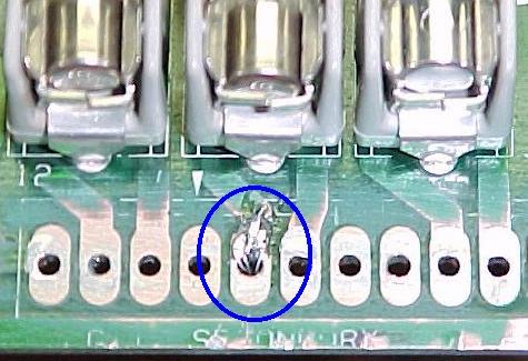
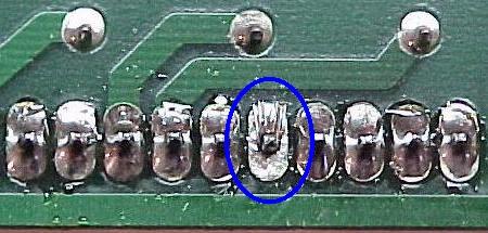
glass for a disconnected or broken or mis-soldered pin.
- Columns are missing from the display (in blocks of 32).
One or more of the column drive chips are defective.
- No display at all.
Display/driver board is defective, or
the correct voltage is not being supplied by the controller board.
- The display is unreadable.
The RAM on the controller
board is defective.
- The display repeats the wrong pattern.
One or more of
the latches going to the RAM on the controller board are defective.
Sound problems and potential solutions.
- No sound.
Usually the AD7524 DAC is defective.
- No speech.
Usually the 55536 CVSD, or the TL040 op-amp,
or the TL082 op-amp are defective.
- The speech is distorted.
Usually a defective 55536 CVSD,
or a defective 74LS74.
- No music.
Usually the YM3012 or the YM2151 are
defective.
- The volume level is too low and the volume control is not the
problem.
Check the TL084 and the TL082 op-amps.
- No output at all.
The LM1875 audio amp is probably
defective. This amp should have -26 volts on pin 3, and +26 volts on
pin 5. Anything else indicates a problem. The sound ROM or RAM could
be defective. There should be high pulses on the output pins of the
Sound ROM and RAM. The MC3340 attenuator can also cause this problem.
- The board is dead.
There is probably no +12 or -12
volts. Check fuse F501 and F502.
- Sound Board Error codes at game power-on:
- 1 beep = sound board Ok
- 2 beeps = U9 RAM failure
- 3 beeps = U18 ROM failure
- 4 beeps = U15 ROM failure
- 5 beeps = U14 ROM failure
|
